Real-Time Counter (S08RTCV1)
MC9S08QE128 MCU Series Reference Manual, Rev. 2
244 Freescale Semiconductor
13.4 Functional Description
The RTC is composed of a main 8-bit up-counter with an 8-bit modulo register, a clock source selector,
and a prescaler block with binary-based and decimal-based selectable values. The module also contains
software selectable interrupt logic.
After any MCU reset, the counter is stopped and reset to 0x00, the modulus register is set to 0x00, and the
prescaler is off. The 1-kHz internal oscillator clock is selected as the default clock source. To start the
prescaler, write any value other than zero to the prescaler select bits (RTCPS).
Three clock sources are software selectable: the low power oscillator clock (LPO), the external clock
(ERCLK) and the internal clock (IRCLK). The RTC clock select bits (RTCLKS) are used to select the
desired clock source. If a different value is written to RTCLKS, the prescaler and RTCCNT counters are
reset to 0x00.
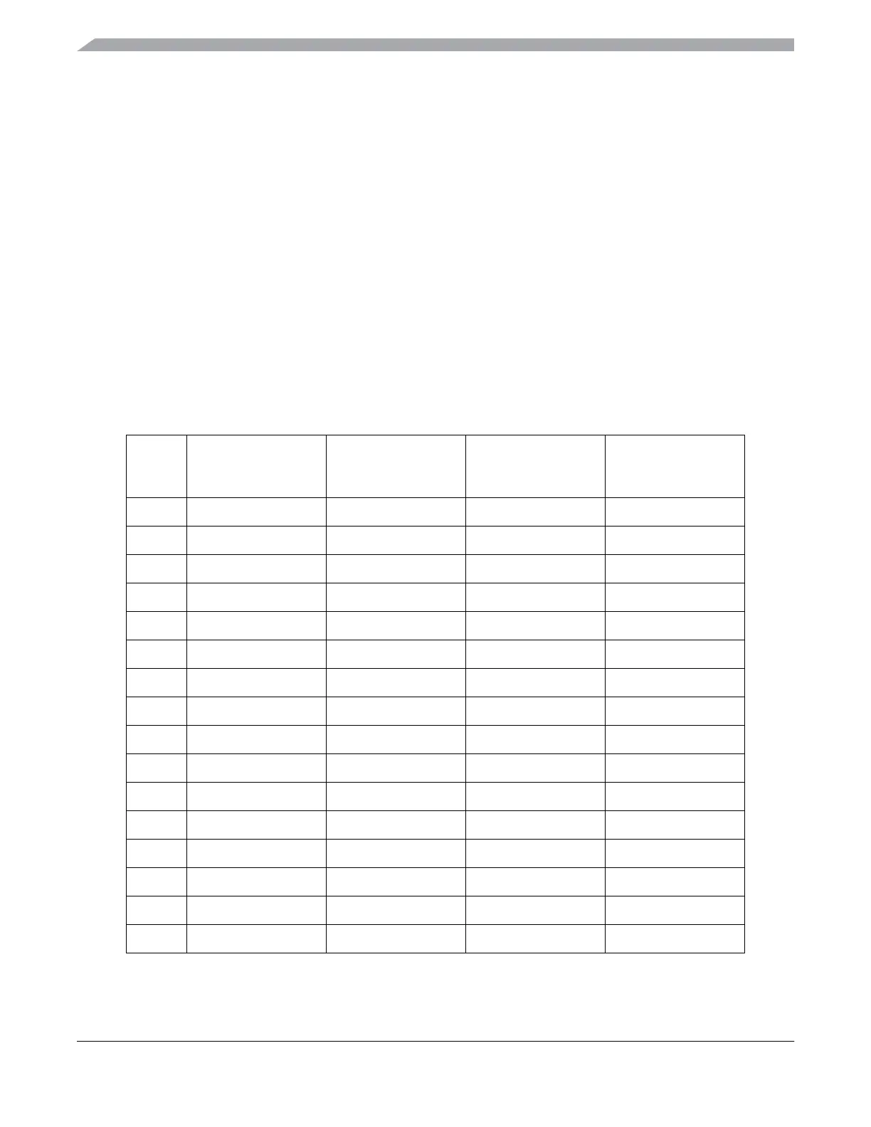
RTCPS and the RTCLKS[0] bit select the desired divide-by value. If a different value is written to RTCPS,
the prescaler and RTCCNT counters are reset to 0x00. Table 13-6 shows different prescaler period values.
Table 13-6. Prescaler Period
RTCPS
1-kHz internal clock
source prescaler period
(RTCLKS = 00)
1-MHz external clock
source prescaler period
(RTCLKS = 01)
32-kHz internal clock
source prescaler period
(RTCLKS = 10)
32-kHz internal clock
source prescaler period
(RTCLKS = 11)
0000 Off Off Off Off
0001 8 ms 1.024 ms 250 μs 32 ms
0010 32 ms 2.048 ms 1 ms 64 ms
0011 64 ms 4.096 ms 2 ms 128 ms
0100 128 ms 8.192 ms 4 ms 256 ms
0101 256 ms 16.4 ms 8 ms 512 ms
0110 512 ms 32.8 ms 16 ms 1.024 s
0111 1.024 s 65.5 ms 32 ms 2.048 s
1000 1 ms 1 ms 31.25 μs 31.25 ms
1001 2 ms 2 ms 62.5 μs 62.5 ms
1010 4 ms 5 ms 125 μs 156.25 ms
1011 10 ms 10 ms 312.5 μs 312.5 ms
1100 16 ms 20 ms 0.5 ms 0.625 s
1101 0.1 s 50 ms 3.125 ms 1.5625 s
1110 0.5 s 0.1 s 15.625 ms 3.125 s
1111 1 s 0.2 s 31.25 ms 6.25 s