Chapter 1 Device Overview
MC9S08QE128 MCU Series Reference Manual, Rev. 2
24 Freescale Semiconductor
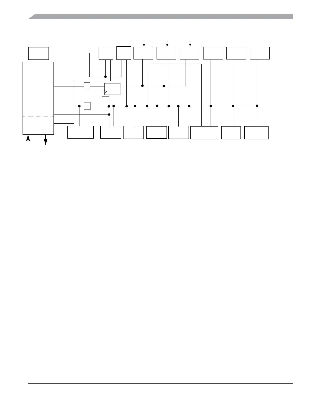
Figure 1-2. System Clock Distribution Diagram
TPM1 TPM2 TPM3 SCI1 SCI2
BDC
CPU
ADC
FLASH SPI2
ICS
ICSOUT
÷2
BUSCLK
ICSLCLK
ICSERCLK
COP
* The fixed frequency clock (FFCLK) is internally
synchronized to the busclock and must not exceed one half
of the bus clock frequency.
Flash has frequency
requirements for program
and erase operation. See
the data sheet for details.
ADC has min and max
frequency requirements.
See the ADC chapter
and data sheet for
details.
XOSC
XTAL XTAL
SPI1
FFCLK*
ICSFFCLK
RTC
1 kHZ
LPO
TPM1CLK
ICSIRCLK
÷2
IIC2
IIC1
DBG
TPM3CLK
SYNC*
LPOCLK
OSCOUT
 Loading...