12-bit Analog-to-Digital Converter (S08ADCV1)
MC9S08QE128 MCU Series Reference Manual, Rev. 2
Freescale Semiconductor 183
10.3.2 Status and Control Register 2 (ADCSC2)
The ADCSC2 register is used to control the compare function, conversion trigger and conversion active of
the ADC module.
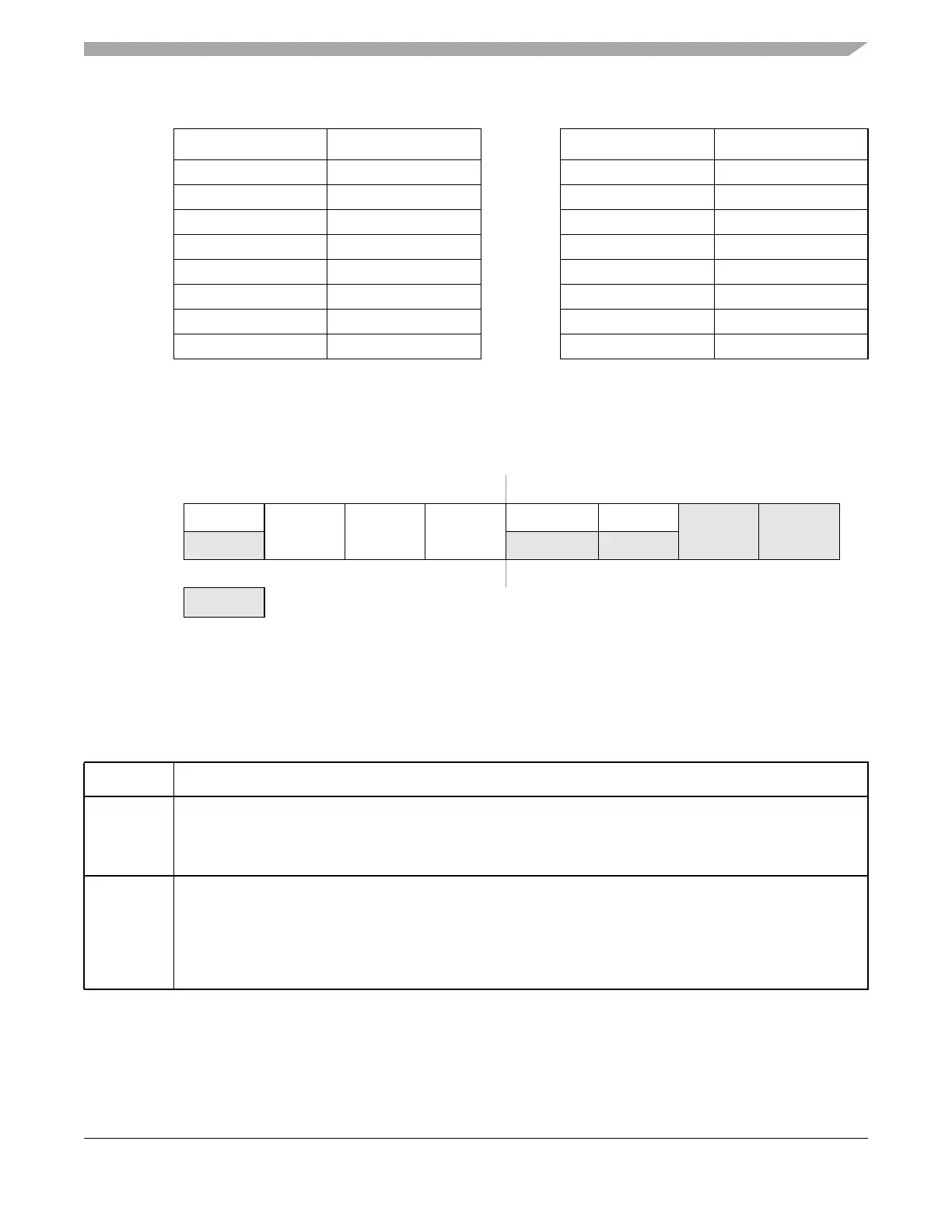
Figure 10-5. Status and Control Register 2 (ADCSC2)
01000 AD8 11000 AD24
01001 AD9 11001 AD25
01010 AD10 11010 AD26
01011 AD11 11011 AD27
01100 AD12 11100
Reserved
01101 AD13 11101
V
REFH
01110 AD14 11110 V
REFL
01111 AD15 11111 Module disabled
7654 3 210
RADACT
ADTRG ACFE ACFGT
00
R
1
1
Bits 1 and 0 are reserved bits that must always be written to 0.
R
1
W
Reset: 0 0 0 0 0 0 0 0
= Unimplemented or Reserved
Table 10-4. ADCSC2 Register Field Descriptions
Field Description
7
ADACT
Conversion Active — ADACT indicates that a conversion is in progress. ADACT is set when a conversion is
initiated and cleared when a conversion is completed or aborted.
0 Conversion not in progress
1 Conversion in progress
6
ADTRG
Conversion Trigger Select — ADTRG is used to select the type of trigger to be used for initiating a conversion.
Two types of trigger are selectable: software trigger and hardware trigger. When software trigger is selected, a
conversion is initiated following a write to ADCSC1. When hardware trigger is selected, a conversion is initiated
following the assertion of the ADHWT input.
0 Software trigger selected
1 Hardware trigger selected
Figure 10-4. Input Channel Select (continued)
ADCH Input Select ADCH Input Select
 Loading...