3.
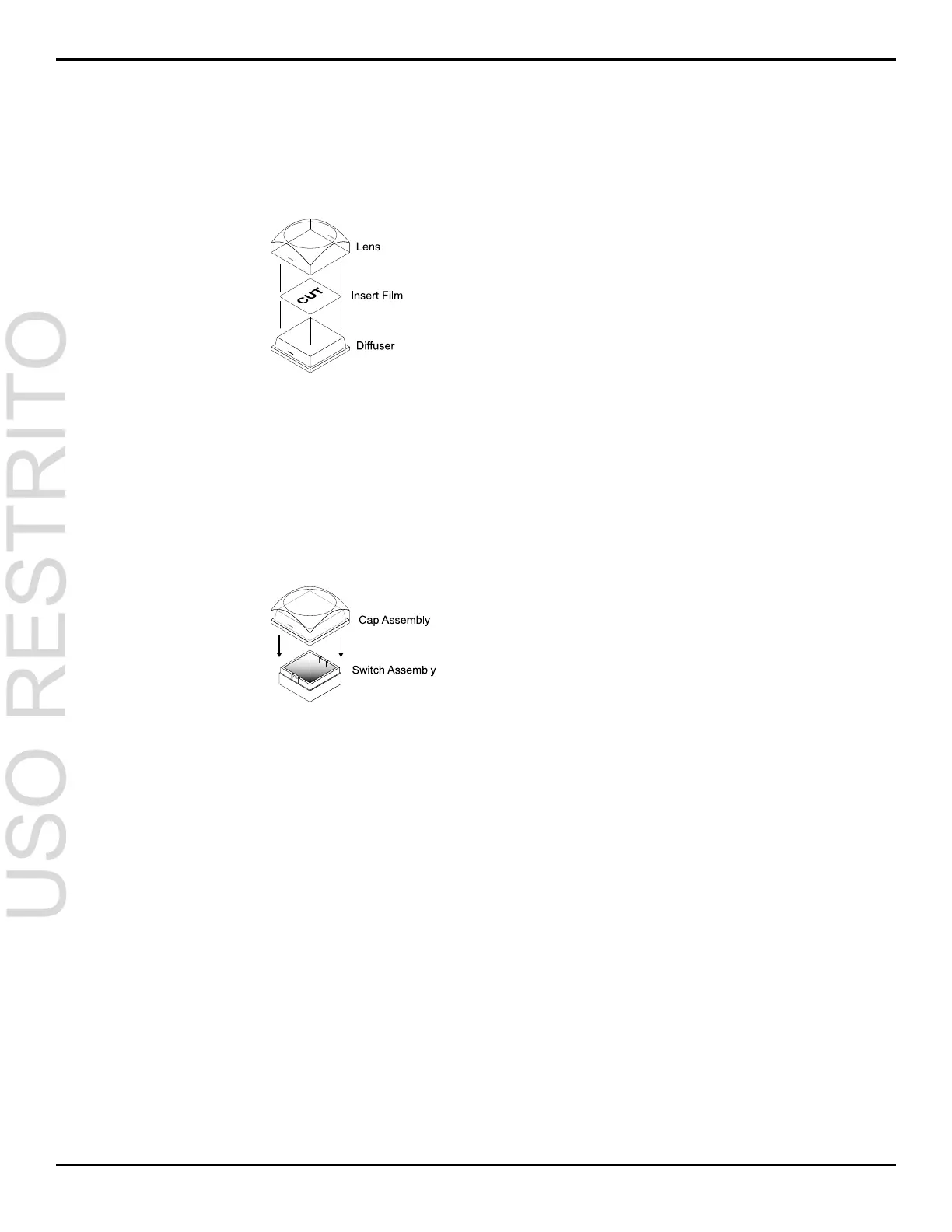
Place the Insert Film into the Lens so the
readable side is facing up. The notches on the
sides of the Lens must be at the sides of the text
on the Insert Film.
Figure 9: Inserting Film
4.
Aligning the notches on the sides of the Lens
and Diffuser, press the Lens and Diffuser
together until they click.
5.
Aligning the notches on the sides of the Cap
Assembly to the tabs on the side of the Switch
Assembly, press Cap Assembly down onto the
Switch Assembly with a rolling motion until they
click together.
Figure 10: Removing Lens from Diffuser
Bus Maps
Any video input can be mapped to any source button on
the control panel using a bus map. There is an editable
bus map and a xed, default, bus map, that can be applied
to all MEs on the switcher. Each source button can have
two inputs assigned (a standard source and a shifted
source).
To Create a Bus Map
All buses and MEs share the same bus map.
1.
Press MENU > CONFIG > BusMap.
2.
Use the XptBtn knob to select the source button
to assign a video source to.
3.
Use the Input knob to select the source to assign
to the selected button on the unshifted bus.
•
<none> — not assigned to a source (cannot
be selected on a bus)
•
BK — black
•
1-24 — video inputs (number of inputs
depends on hardware)
•
M1-M4 — Media-Store channels
•
MXMW — ME 1-2 MediaWipe preview
•
MXMWA — ME 1-2 MediaWipe alpha
•
BG — matte generator
•
PGM — main program output of the switcher
(cannot be selected on an ME/MultiScreen)
•
PV — main preview output of the switcher
(cannot be selected on an ME/MultiScreen)
•
CLN — main clean feed output of the
switcher (cannot be selected on an
ME/MultiScreen)
•
MEX — ME 1-2 re-entry (cannot be selected
on the same or lower number ME)
•
MEX PV — ME 1-2 preview (cannot be
selected on the same or lower number ME)
•
MEX CLN — ME 1-2 clean feed (cannot be
selected on the same or lower number ME)
•
AUX1-8 — Aux bus 1-8
•
MV1-2 — MultiViewer 1-2 (cannot be
selected on ME/MiniME
™
)
•
MinME1-4 — MiniME
™
1-4 program
(cannot be selected on an ME)
•
Shift — access shifted bus
4.
Use the Shift knob to select the source to assign
to the selected button on the shifted bus.
To Reset the Bus Map
1.
Press MENU > RESET > NEXT > NEXT.
2.
Press the Dfault BusMap knob.
3.
Press the Confrm knob to reset the bus map.
GPI Device Control
You can assign a GPI output to a video source for basic
external device control. When a video source is taken
on-air, the switcher can be set to trigger a GPI output,
with a pre-delay. The external device can be set up to
cue a clip, or load a page when it receives the GPI input
trigger.
To Assign a GPI to a Video Source
1.
Press MENU > CONFIG > Input > NEXT >
NEXT > NEXT.
22 • Video Input Setup — Carbonite Setup Manual (v10.0)

 Loading...


