To Run the RAM Test
The switcher can be set to perform a RAM test every
time it powers on. To enable this feature, set DIP switch
1 in the frame to the down position.
Note: When a RAM test is started, it must be allowed to finish.
If the test is interrupted by a power cycle, the test will continue
when the switcher powers on again. This may appear as if the
switcher is failing to power on correctly, or is stuck in an
upgrade.
1.
Press MENU > SYSTEM > NEXT > NEXT >
Diag Tests > NEXT > RAM Test.
The top line of the menu shows the result of the
last RAM test.
2.
Press the Reboot knob to run the test.
The switcher runs the test and then reboots.
3.
The results of the test are shown on the top line
of the menu.
4.
Press MENU to end the test.
To Run the Tally Test
The Tally Test turns all tallies off, and then turns each
tally on consecutively. There is a three (3) second delay
between each tally being toggled on. Once the last tally
has been turned on, all the tallies blink on and off three
times.
1.
Press MENU > SYSTEM > NEXT > NEXT >
Diag Tests> NEXT > NEXT > Tally Test.
All tallies are turned off, and then each tally is
turned on consecutively. There is a three (3)
second delay between each tally being toggled
on. Once the last tally has been turned on, all the
tallies blink on and off three times.
2.
Press MENU to end the test.
To Run the GPI Input Test
1.
Press MENU > SYSTEM > NEXT > NEXT >
Diag Tests > NEXT > NEXT > GPI Test.
The second line of the menu show the state of
all GPI input pins as High or Low.
2.
Press MENU to end the test.
To Run the GPI Output Test
1.
Press MENU > SYSTEM > NEXT > NEXT >
Diag Tests > NEXT > NEXT > GPO Test.
All GPI outputs are turned off, and then each one
is turned on consecutively. There is a three (3)
second delay between each GPI output being
triggered. Once the last tally has been triggered,
all the GPI outputs blink on and off three times.
2.
Press MENU to end the test.
Error Messages
The following error messages may appear when starting
your switcher.
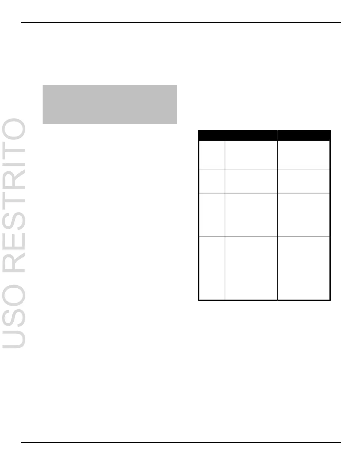
Table 8: Switcher Error Messages
SolutionDescriptionError
Re-start your switcher. If the
problem persists, contact
There is a problem with the
switcher DDR memory. The
DDR 0 Not
Found; DDR
Ross Video Technical
Support for assistance.
switcher may be used but
many features will be limited
or disabled.
1 Not Found;
or DDR 0 & 1
Not Found
Connect your switcher
control panel to the proper
Your switcher control panel
is connected to the wrong
frame type.
Panel/Frame
Mismatch
frame and re-start the
switcher.
Allow the PMC upgrade to
proceed. Contact Ross
Your switcher requires a
Panel Module Controller
Upgrade
PMC?
Video Technical Support for(PMC) upgrade as part of a
assistance if you are unsuresoftware upgrade. The
about upgrading your
switcher.
switcher may be used
without the PMC upgrade
but may respond in an
unpredictable manner.
Ensure that you have the
correct control panel
The frame does not
recognise the control panel.
Unknown
panel type
connected to the frame. IfThis could be caused by anPlease
upgrade the problem persists,
download the latest upgrade
unsupported panel being
connected to the frame, or
file from and force ana problem with the panel
upgrade of the switcher.module controlled or the
configuration files. Contact Ross Video
Technical Support for
assistance if you are unsure
about upgrading your
switcher.
48 • Diagnostics and Calibration — Carbonite Setup Manual (v10.0)

 Loading...


