System Real-Time Clock
The switcher uses an internal clock to generate the time
for the clock overlay for the MultiViewer.
To Set the System Real-Time Clock
1.
Press MENU > CONFIG > NEXT > Clock.
2.
Press Edit.
3.
Use the Hour, Minute, and Second knobs to
select the current time.
4.
Press the Hour knob.
5.
Press the Confrm knob.
Diagnostics
Diagnostics consist of a number of tests that are used to
conrm the functionality of switcher components.
Frame Diagnostic LEDs
There are a number of LEDs inside the frame that are
used to diagnose the operation of the switcher.
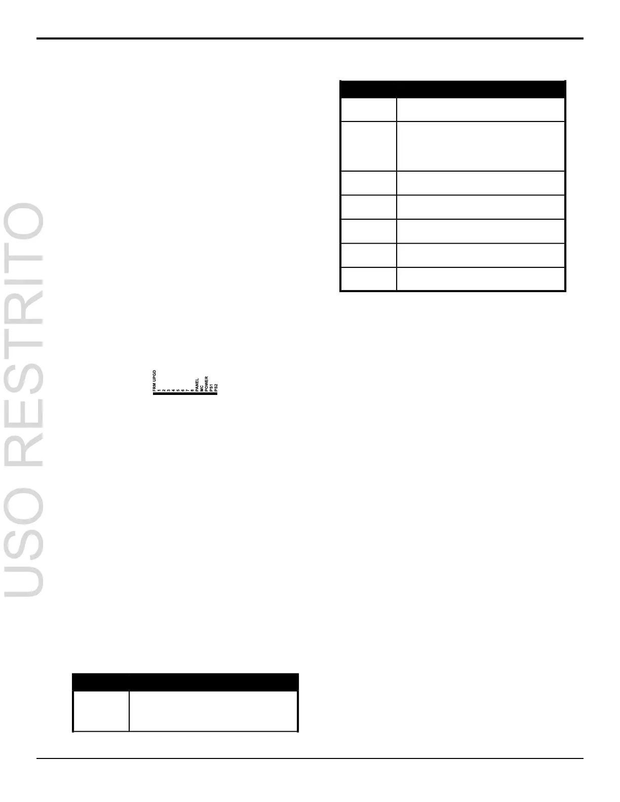
Figure 13: Frame Diagnostic LEDs
• FRM UPGD — is lit when the software on the
frame is being upgraded
• 1 (heartbeat) — ashes to indicate normal
operation of the frame
• 2 - 8 — unused
• PANEL — is lit when the frame has proper
connection to the control panel
• MC — is not used at this time
• POWER — is lit when the frame is on
• PS1 — is lit when power supply one is getting
power
• PS2 — is lit when power supply two is getting
power
Frame DIP Switches
There are a number of DIP switches inside the frame that
are used to diagnose the operation of the switcher.
Table 7: Frame DIP Switches
DescriptionDIP
This DIP switch forces a RAM test every time the
switcher is powered on. It is in the up (off) position by
1
default. Refer to To Run the RAM Test on page 48
for more information.
DescriptionDIP
This DIP switch is unused and should be left in the
default up (off) position.
2
This DIP switch is used to set the IP address of the
frame to the default value (192.168.0.123). It must be
3
in the up (off) position to set another IP address for
the frame. Refer to Network Setup on page 40 for
more information.
This DIP switch prevents software upgrades. It must
be in the up (off) position to upgrade the switcher.
4
This DIP switch is unused and should be left in the
default up (off) position.
5
This DIP switch is unused and should be left in the
default up (off) position.
6
This DIP switch is unused and should be left in the
default up (off) position.
7
This DIP switch is unused and should be left in the
default up (off) position.
8
To Run the Control Panel Test
Test the functionality of any of the buttons, knobs or
fader and positioner on the control panel.
1.
Press MENU > SYSTEM > NEXT > NEXT >
Diag Tests > Contrl Test.
The second line of the display shows the current
button, knob, positioner, or fader being used.
2.
Test the button, knob, positioner, and fader you
want to check.
3.
Press the MENU and Exit buttons at the same
time to end the test. Press MENU and RESET
on the C1/C10.
To Run the LED Test
1.
Press MENU > SYSTEM > NEXT > NEXT >
Diag Tests > P-LEDs Test.
All the buttons and indicators on the control
panel cycle through different colors.
2.
Press MENU to end the test.
To Run the Display Test
1.
Press MENU > SYSTEM > NEXT > NEXT >
Diag Tests > Disply Test.
A series of letters, numbers, and symbols scroll
across the displays and the mnemonics cycle
colors.
2.
Press MENU to end the test.
Carbonite Setup Manual (v10.0) — Diagnostics and Calibration • 47

 Loading...


