Installation & Maintenance Instructions
14
LOCAL
POS
I
T
‘UP’ ‘DOWN’ ‘MODE/CANCEL’ ENTER
POS
I
T
REMOTE
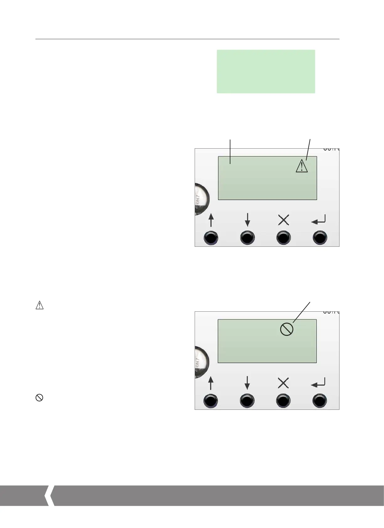
Remote Mode Selected Alarm Active
‘UP’ ‘DOWN’ ‘MODE/CANCEL’ ENTER
Critical Fault Alarm
POS
I
T
LOCAL
VIEW
5.2.7 LCD Display
The main PCB has a LCD Display used to show STATUS and
configuration information.
On power up the default screen is the POSIT parameter.
The actuator will indicate Local or Remote mode selected in
top left hand corner of the LCD.
See Basic Setup Mode for details.
5.2.8 Setup Pushbuttons
Four push button switches are located on the main PCB
below its LCD Display and are used to view and change the
actuator configuration parameters.
The Switch Functions are as follows:
‘UP’
Used to navigate menus in view mode. Increase parameter
values in Edit Mode.
‘DOWN’
Used to navigate menus in view mode. Decrease parameter
values in Edit Mode.
‘MODE/CANCEL’
Used to exit and go to previous Menu.
ENTER
Used to enter and save changes to configuration parameters.
NON-CRITICAL FAULT
An alarm condition exists which does not prohibit actuator
movement.
Non-critical faults are:
STALL
Torque / Thrust Overload
Loss of Communications
Loss of Demand Signal
Over Temperature
Power Loss
CRITICAL FAULT
An alarm exists which prohibits actuator movement.
Critical faults are:
Loss of Feedback
EEPROM Fault
5. Installation & Setup
Fig 5.8
Fig 5.9
Fig 5.10
A4US
US
A4
US A4
US
A4
 Loading...

