15
The CMA actuator is available for linear, quarter-turn or
rotary valves, dampers or other devices.
Each of these applications may require different methods of
mounting the actuator to the valve.
Typical examples only are described in this publication and do
not cover all possible variants of valve types.
6.1 CML - Linear Unit - Mounting
CAUTION
It is essential that the actuator mounting procedure
is carried out when the valve is not under working
process conditions, as full valve movement may occur.
IMPORTANT
It is essential that the actuator is mounted correctly to
the valve.
The height of the yoke or pillar and mounting plate, in
relation to the top of the valve spindle is critical to ensure full
stroke movement of the valve.
The Installation & Setup will include the following procedures:
1. Ensure valve is closed and safe (offline)
2. Actuator output shaft is retracted
3. Mount and align actuator to valve
4. Carry out basic setup
WARNING
Where actuators are fitted with Reserve Powerpack
assembly please note that the actuator output shaft
may move after removal of the power supply.
After disconnection of the power supply wait until
the flashing Red/White External LCD display has
extinguished before removal of the top cover assembly
to gain access to the electrical compartment of the
actuator!
WARNING
Under NO circumstances attempt to move the actuator
or adjust the output drive shaft connection to the valve
stem whilst the External Local display is illuminated.
DO NOT REMOVE THE TOP COVER ASSEMBLY TO GAIN
ACCESS TO THE ELECTRICAL COMPARTMENT WHILST
THE LOCAL DISPLAY IS ILLUMINATED.
WAIT UNTIL THE DISPLAY IS EXTINGUISHED, THIS
COULD TAKE UP TO 30 MINUTES AFTER POWER DOWN.
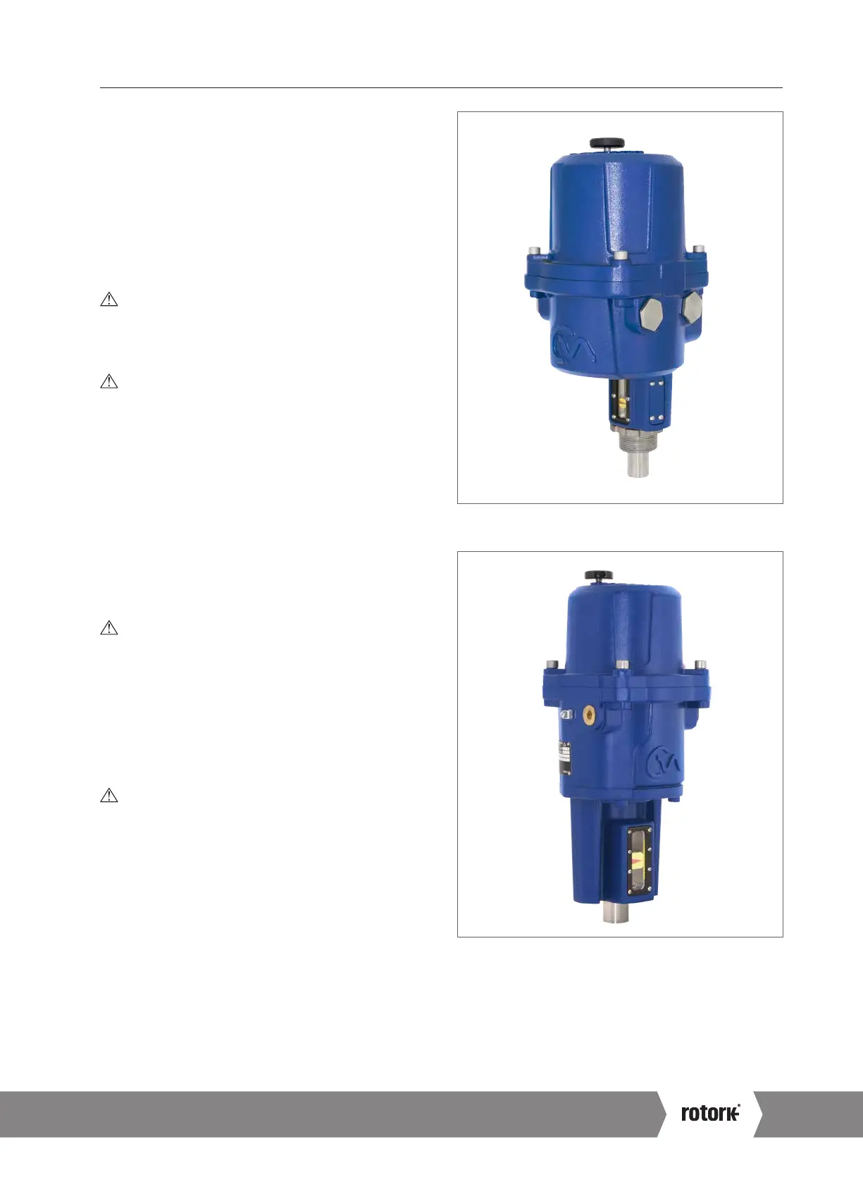
6. Mounting the Actuator – CML Linear Actuators Only
Fig 6.1 CML-10 0 & CML-250
Fig 6.2 CML-750
A4 US
US
A4
US
A4
A4 US
 Loading...

