Installation & Maintenance Instructions
16
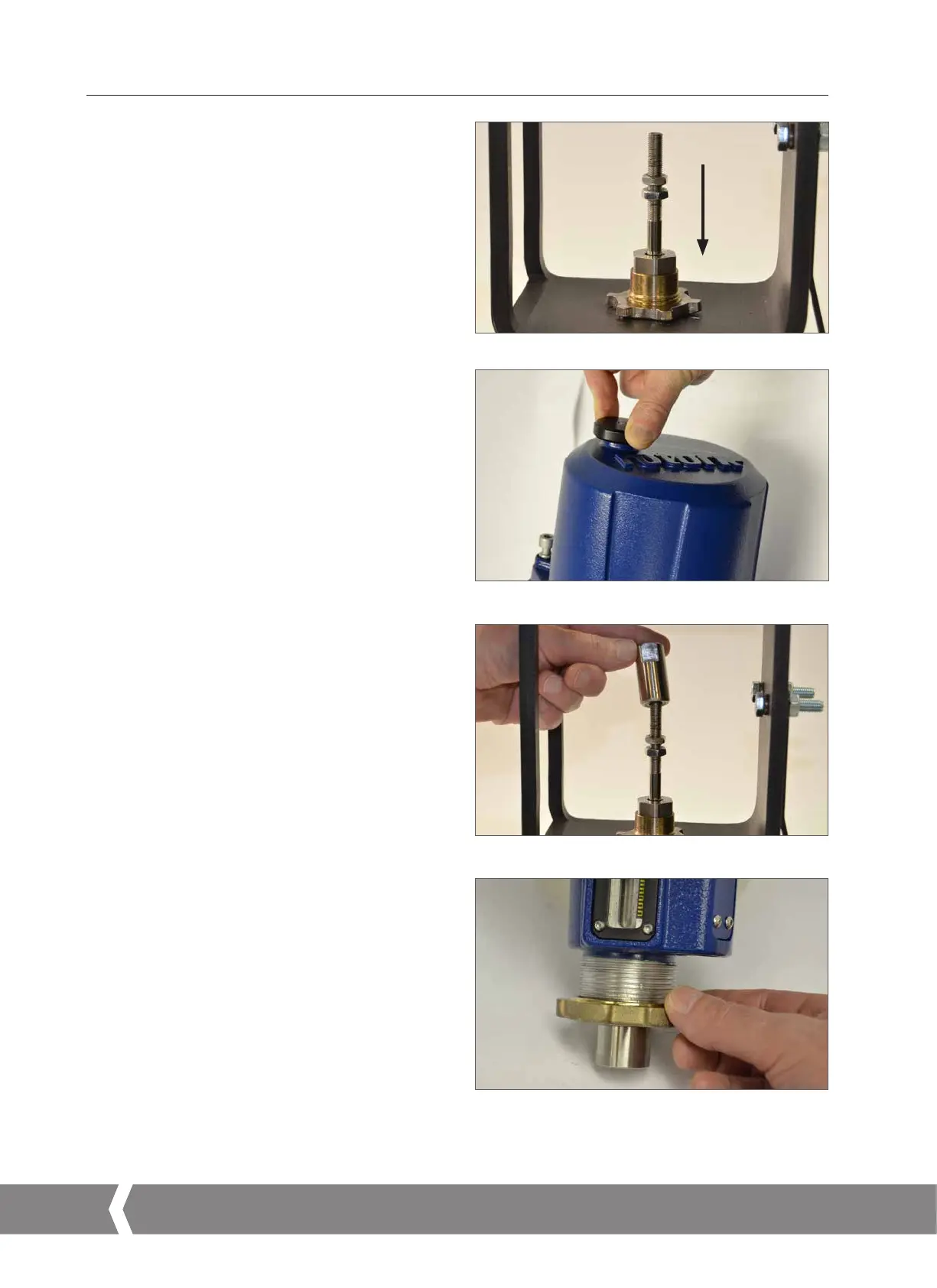
6. Mounting the Actuator – CML Linear Actuators Only
Move Valve stem to the closed position
To enable the actuator to be installed correctly the valve must
be in the closed (down) position to allow fitting of the valve
stem/actuator coupling.
Actuator Output Shaft
The actuator is supplied with the output shaft in the fully
retracted position. If the output shaft is in the extended
position it may be necessary to manually operate the actuator
using the handwheel to the retracted position to allow
installation. Push and turn the handwheel to retract the
output shaft.
Valve Stem Coupling
Machine the valve stem to actuator output shaft coupling
adaptor to suit. (NOT SUPPLIED)
Fit the coupling to the valve stem. It may be necessary to use
a locking nut to eliminate any backlash.
Leave the coupling loose and free to rotate at this stage.
CML-100 & CML-250 Units Only
Remove the locking ring from the base of the actuator and
position the unit on to the valve mounting flange.
CML-750 Units
Position the actuator on to its mounting flange, fit four off
fixings but do not fully tighten at this stage.
Fig 6.3
Fig 6.4
Fig 6.5
Fig 6.6
A4US
US
A4
US A4
US
A4
 Loading...

