Installation & Maintenance Instructions
54
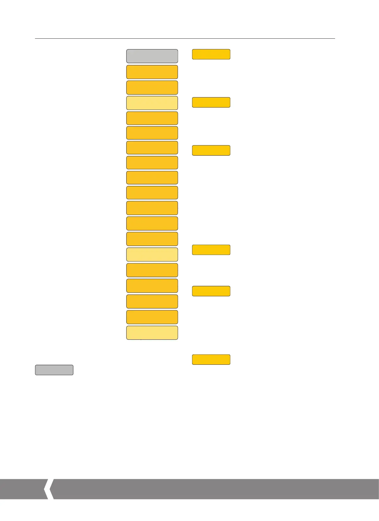
15. Advanced Menu
CPT 4
15. 2.1 CPT 4 Current Position Transmitter - Zero
Adjustment
Connect a suitable meter. Enter Edit mode and use the
UP/DOWN pushbuttons to adjust the 4 mA (ZERO) output.
CPT 20
15.2.2 CPT 20 Current Position Transmitter - Span
Adjustment
Connect a suitable meter. Enter Edit mode and use the
UP/DOWN pushbuttons to adjust the 20 mA (SPAN) output.
SPEED
15.2.3 SPEED - Adjust Actuator Output Speed
Actuator output speed is adjustable between 50% and 100%
of its rated speed. Default is 100%.
CMR UNITS ONLY:
TURNS - Set the number of full turns from the Close end
of travel limit position. Always configure the Close
limit prior to setting turns.
OP DIR - The operating direction is automatically determined
during the basic setup process. Use this parameter
to manually configure operating direction.
STL TO
15.2.4 STL TO - Stall Time
Motor stall time adjustable between 1 to 10 seconds.
DEFAULT is 2 seconds.
KB DIS
15.2.5 KB DIS - Knob Disable
The local control knobs can be disabled using this setting.
Setting OFF will maintain normal operation of the local
control knobs. Setting ON will disable the local control knobs
and prevent operating mode changes. Operating mode is set
with the internal HMI. The external display will continue to
provide position and status feedback.
FHSTCL
15.2.6 FHSTCL - Fault History Clear
Enter Edit mode. The CONFIRM parameter is now displayed,
press Enter to clear the stored fault history.
ADVANCED SETTINGS
CPT 4 - Current POS
Transmitter - Zero/4 ma
CPT 20 - Current POS
Transmitter - SPAN (20 mA)
SPEED - Adjust Actuator
Output Speed
TURNS - CMR ONLY
OP DIR - CMR ONLY
STL TO - STALL TIME
KB DIS - Knob Disable
FHSTCL - Fault History Clear
CMDSRC - COMMAND SOURCE
INFO
CTRCFG - CONTROL
CONFIGURATION
RELAYS - RELAY
CONFIGURATION
DIG INPUTS - Configure Digital
Inputs (if fitted)
SPLTRG - SPLIT RANGE
ACT CFG - ACTUATOR
CONFIGURATION
UPS - Configure settings for the
Reserve Power Pack (if fitted)
INTTIM - Timer Interrupt
COMMS - Configure COMMS
Option Cards (if fitted)
INTTIM
CL TIE
ST CLS
SP OPN
CL OFF
ST OPN
SP CLS
OP ON
OP OFF
CL ON
OP TIE
SPEED
CPT 20
CPT 4
INTTIM
ADVANC
INFO
ST ACT
AMP ST
TEMP
SW VER
POSIT
Position
SET PT
Setpoint
THRUST or TORQUE
Thrust Display or
Ouput Torque
LOCREM
Local / Remote Operation
MANJOG
Manual Jog
TORQ/THRSTC
Close Torque/Thrust
TORQ/THRSTO
Open Torque/Thrust
CL ACT
Close Action
OP ACT
Open Action
BASIC
CL LIM
Close Limit (zero)
OP LIM
Open Limit (span)
CMD4
Field Command Signal4
CMD20
Field Command Signal20
DBAND
Deadband
FLTHST
Fault History Access
ADVANC
Advanced Menu
DEFLTS
Default Menu Access
STATUS
CTRCFG
CTRLAL
IN DMP
LOS TO
LOS ACT
LOS LO
LOS HI
ACTCFG
RELAYS
R1 CFG
R1 FRM
R2 CFG
R2 POS
ACTTYP
ACTSIZ
ENCINI
SPLTRG
MINCMD
MAXCMD
BSRACT
ASRACT
ASPOS
BSRPOS
UPS
LOP AC
LOP PO
LOP TO
OR REM
OR LOC
OR LST
LOP SP
DEFLTS
LD CUST
ST CUST
LD FACT
R2 FRM
R1 POS
R5 CFG
R5 FRM
R6 CFG
R6 POS
R6 FRM
R5 POS
R7 CFG
R7 FRM
R8 CFG
R8 POS
R8 FRM
R7 POS
D1 CFG
D2 CFG
D2 FRM
D3 CFG
D3 FRM
D4 CFG
D4 FRM
D1 FRM
DIG IN
PRM OC
Primary Option
RI CTL
Remote Control Inputs
2W PRI
2 Wire Priority
LOS AC
RIRO Only
LOS PO
RIRO Only
ESDACT
ESD Action
ESDOLS
ESD Override Local Stop
KNBMNT
Local Maint
CMDSRC
INFO
RELAYS
DIG IN
SPLTRG
ACT CFG
UPS
CTRCFG
Control Setup
CMDSRC
STL TO
TURNS***
OP DIR***
KB DIS
Knob Disable
FHSTCL
COMMS
MODBUS
PROFIBUS
PAKSCAN
HART
FFBUS
DEVICENET
FOLOMATIC
COMMS
COM TO
LOS ACT
LOS PO
MIN SP
MAX SP
CMD IV
Command Invert
CPT IV
Transmitter Invert
ADVANC
15.2 Advanced Menu
Parameters can only be changed with actuator selected to
Local Operation Mode.
Press UP/DOWN pushbuttons until ADVANC menu is displayed.
Press Enter to gain access to the Advanced Menu parameters.
Use the UP/DOWN pushbuttons to scroll to the parameter
you wish to modify. Press 'Enter' to go to Edit Mode.
Use the UP/DOWN pushbuttons to modify the parameter
setting. Press Enter again to store selection. The display will
confirm that your selection has been SAVED.
Press Cancel to return to previous menu.
A4US
US
A4
US A4
US
A4
 Loading...

