Installation & Maintenance Instructions
18
7. Mounting the Actuator – CMQ Quarter-Turn Actuators Only
7.1 CMQ - Quarter-Turn Unit - Mounting
CAUTION
It is essential that mounting procedure is carried
out when the valve is not under working process
conditions, as full valve movement may occur.
IMPORTANT
It is essential that the actuator is mounted correctly to
the valve, damper or other device.
The Installation & Setup will include the following procedures:
1. Prepare the drive coupling
2. Ensure valve position is noted and safe (offline)
3. Mount and align actuator to valve
4. Adjust actuator stop bolts
5. Carry out basic setup
WARNING
Where actuators are fitted with Reserve Powerpack
assembly please note that the actuator output shaft
may move after removal of the power supply.
After disconnection of the power supply wait until
the flashing Red/White External LCD display has
extinguished before removal of the top cover assembly
to gain access to the electrical compartment of the
actuator!
WARNING
Under NO circumstances attempt to move the actuator
or adjust the output drive shaft connection to the valve
stem whilst the external local display is illuminated.
DO NOT REMOVE THE TOP COVER ASSEMBLY TO GAIN
ACCESS TO THE ELECTRICAL COMPARTMENT WHILST
THE LOCAL DISPLAY IS ILLUMINATED.
WAIT UNTIL THE DISPLAY IS EXTINGUISHED, THIS
COULD TAKE UP TO 30 MINUTES AFTER POWER DOWN.
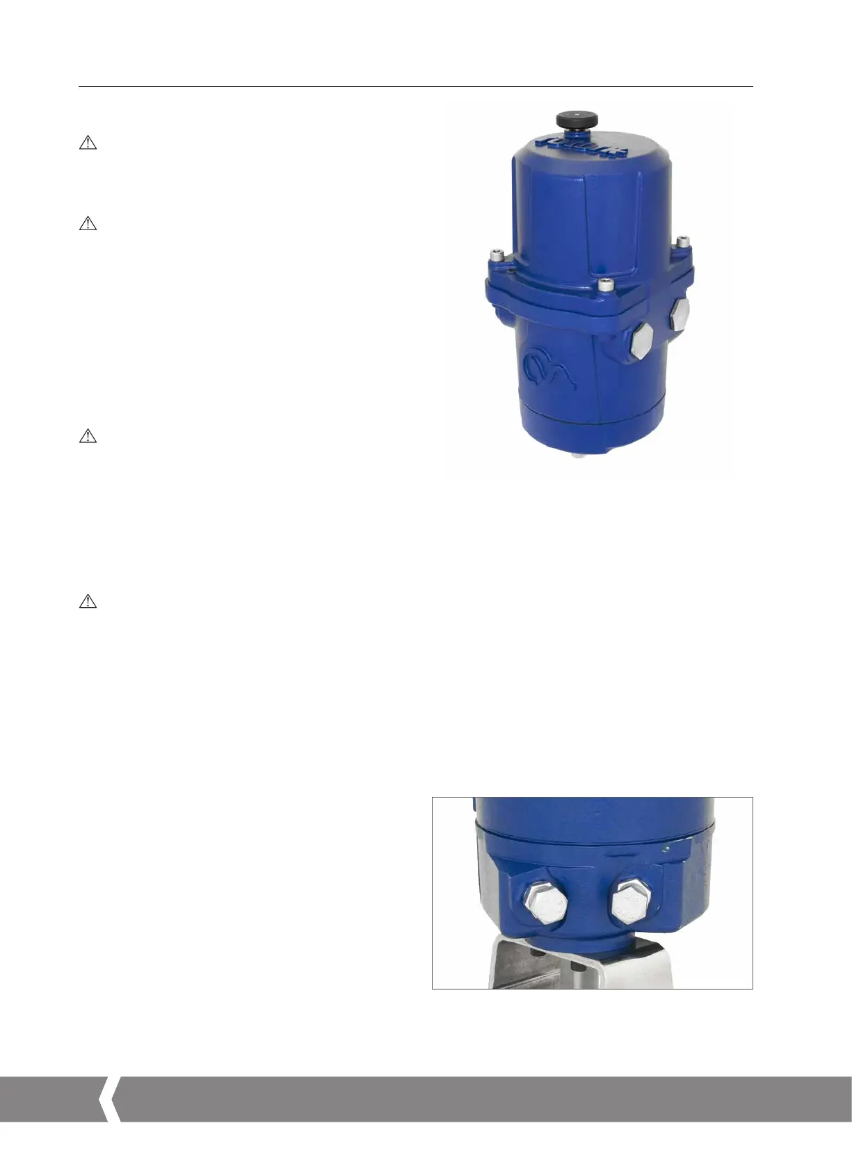
Actuator Stop Bolts
The quarter-turn CMQ actuators have two end of travel stop
bolts adjustable between 80 to 100° of travel rotation.
The stop bolts are set to a nominal 90° of travel at the
factory. These must be adjusted to suit the required valve
travel BEFORE attempting to set the electrical travel limits.
The clockwise end of travel stop bolt is on the right as viewed
in Fig 7.2.
Fig 7.1
Fig 7.2
A4US
US
A4
US A4
US
A4
 Loading...

