23
9. Installation & Setup – All CMA Units
9.1 Electrical Installation
9.1.1 Cable Entries
The cable entries are tapped either ¾” NPT or M25. Remove
any transit plugs. Make off cable entries appropriate to the
cable type and size. Ensure that threaded adaptors, cable
glands or conduit are tight and fully waterproof. Seal unused
cable entries with steel or brass threaded plugs.
If the actuator is to be installed in a hazardous area, a suitably
certified cable gland must be fitted with the use of a certified
thread adaptor where appropriate.
Unused entries must be closed with a suitably certified
stopping plug.
Wire type must meet local and certifying agency (CSA,
IEC Ex, ATEX, etc) requirements and have a minimum
temperature rating of 88 °C.
Wiring installation must comply with local statutory
regulations.
9.1. 2 Connecting to Terminals
The wiring diagram supplied is particular to each actuator and
must not be interchanged with any other actuator. If in doubt
check the wiring diagram number with that on the actuator.
Refer to the wiring diagram to identify functions of terminals.
Check that the supply voltage is the same as that marked on
the actuator nameplate.
9.1.3 Cover Removal Precautions
WARNING
Where actuators are fitted with Reserve Powerpack
assembly please note that the actuator output shaft
may move after removal of the power supply.
After disconnection of the power supply wait until
the flashing Red/White External LCD display has
extinguished before removal of the top cover assembly
to gain access to the electrical compartment of the
actuator!
WARNING
Under NO circumstances attempt to move the actuator
or adjust the output drive shaft connection to the valve
stem whilst the External Local display is illuminated.
DO NOT REMOVE THE TOP COVER ASSEMBLY TO GAIN
ACCESS TO THE ELECTRICAL COMPARTMENT WHILST
THE LOCAL DISPLAY IS ILLUMINATED.
WAIT UNTIL THE DISPLAY IS EXTINGUISHED, THIS
COULD TAKE UP TO 30 MINUTES AFTER POWER DOWN.
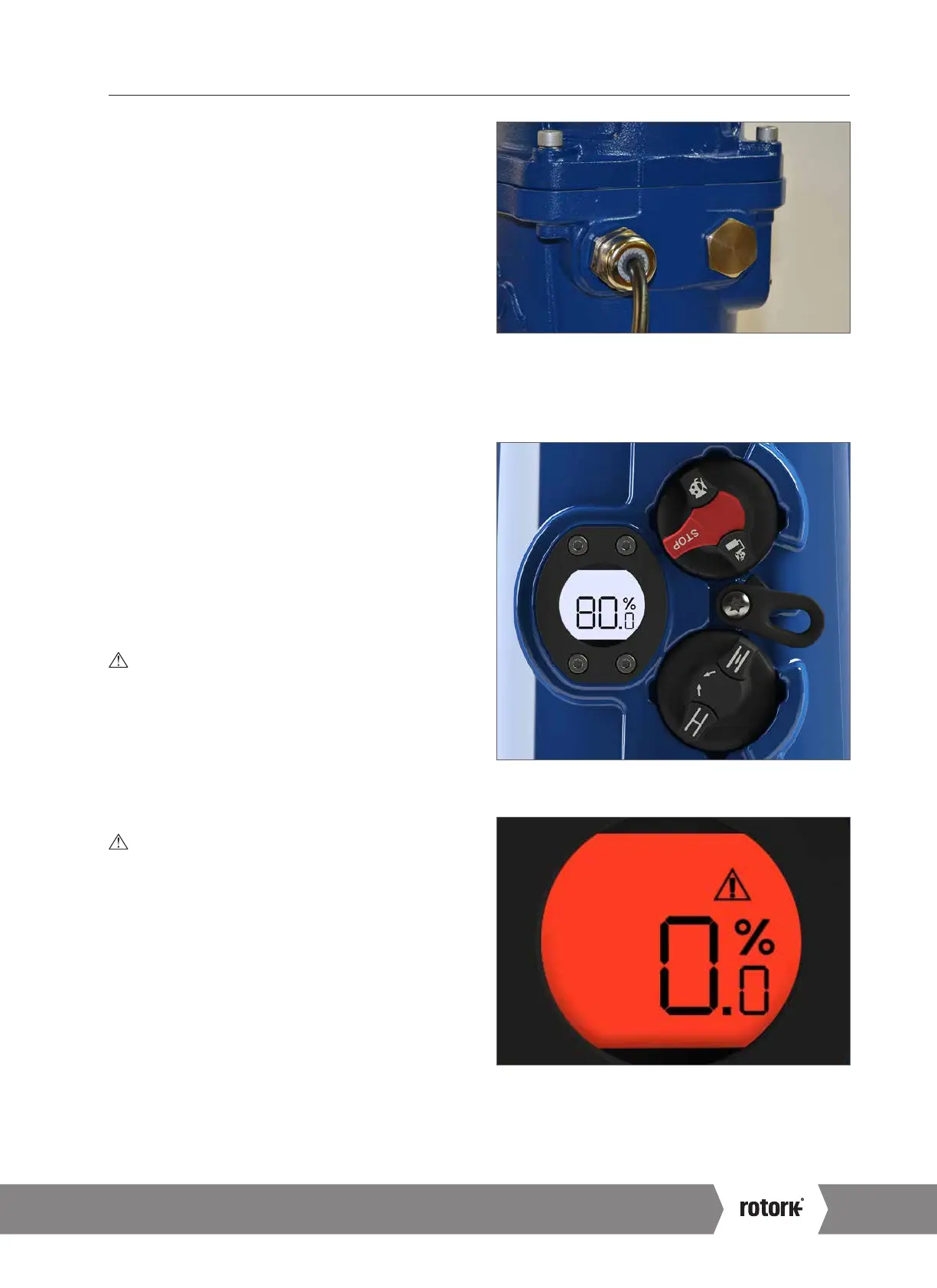
Fig 9.1
Fig 9.2 Actuator set to 'STOP' position
Fig 9.3 Actuator display
flashes Red and White
when RPP is active during power failure.
A4 US
US
A4
US
A4
A4 US
 Loading...

