Installation & Maintenance Instructions
24
9. Installation & Setup – All CMA Units
9.1.4 Electrical Installation
WARNING
Ensure all power supplies are isolated before removing
actuator covers.
Check that the supply voltage agrees with that stamped on
the actuator nameplate. A fused switch or circuit breaker
must be included in the wiring installation of the actuator.
The switch or circuit breaker must be installed as close as
possible to the actuator and shall be marked to indicate that
it is the disconnecting device for that particular actuator.
Actuator must be mounted such that it is not difficult to
operate the disconnecting device.
The actuator must be protected with an over current
protection device rated in accordance with PUB094-001
which details the electric motor performance data for CMA
range actuators.
9.1.5 Earth Ground Connections
A lug is cast adjacent to the conduit entries for attachment of
an external protective Earth (Ground) cable. An internal earth
terminal is also provided. Consult local and certifying agency
codes to determine which earth connectors is to be used.
See Fig 9.4.
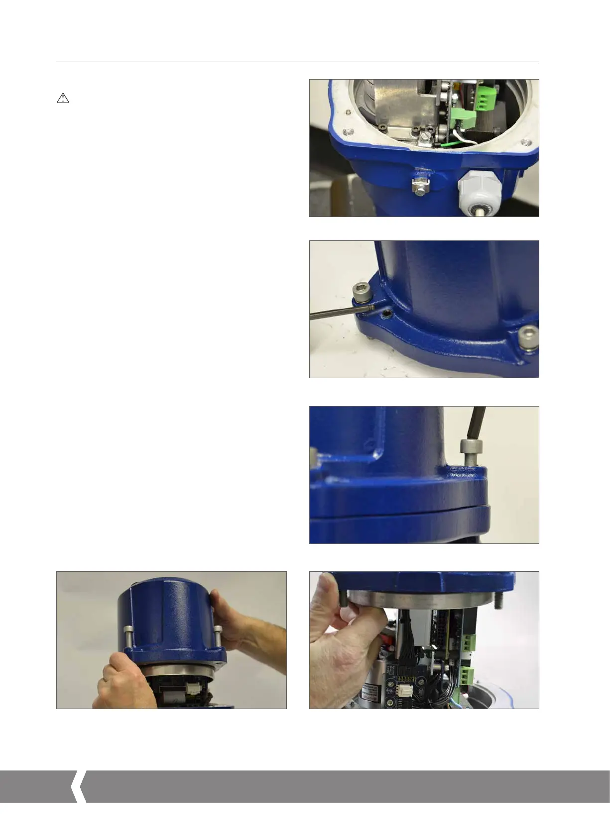
9.1.6 Removing Terminal Cover
Using a 6 mm Allen key loosen the captive fixings securing
the terminal compartment cover. Do not attempt to lever off
the cover with a screwdriver as this will damage the o-ring
seal and may damage the flamepath on a certified unit.
If necessary locate the two set screws Fig 9.5 and use them
to lift the cover away from its seat.
Note: Actuators fitted with Local Controls or Reserve Power
pack have internal wiring loom connectors between the top
cover assembly and the main PCB. See Fig 9.8
.
When removing the top cover assembly support the weight
of the cover and disconnect the wiring loom plug from the
socket located on the main chassis plate before completely
removing the cover.
Fig 9.4
Fig 9.5
Fig 9.6
Fig 9.7 Fig 9.8
A4US
US
A4
US A4
US
A4
 Loading...


