pag. 18
Push buttons and displays
ST2 User’s Manual
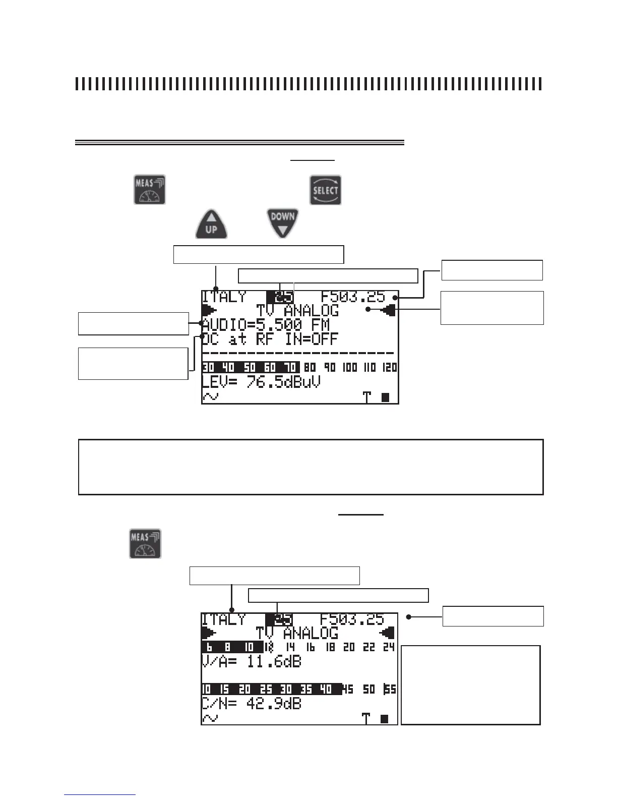
TV Mode
Press the
key and then use the
key to choose the fi eld to be
modifi ed. Use keys
and
to modify the displayed value
3.1 Analogue level measurement (Level 1)
Fig. 3.1 Analogue signal First Measurement Level
Memory plan (see section 1.0)
Channel (see section 1.0)
Analogue or digital mod-
ulation: COFDM (DVB-T/
H), FM Radio
AUDIO FREQUENCY CARRIER
DC at RF IN
Channel frequency
4.2 A/V and C/N analogue measurement (Level 2)
Fig. 3.2 Second Measurement level: V/A and C/N ratio.
NOTES
• lt is only possible to change all the tuning parameters in the fi rst mesurement level, shown in fi g.
3.1 and only for the user generated plans.
• You can return to the fi rst measurement level at any time by pressing the ON/OFF [1] key.
Press the
again to display the second measurement level:
Memory plan (see section 1.0)
Channel (see section 1.0)
Channel Frequency
continuation: ANALOGUE TV SIGNAL MEASUREMENTS: MEAS
NOTE
There are three variable fi elds
in this measurement level:
Memory plan, channel
number and frequency.