pag. 39
Push buttons and displays
ST2 User’s Manual
Satellite Mode
continues: SATELLITE SIGNAL MEASUREMENTS: MEAS
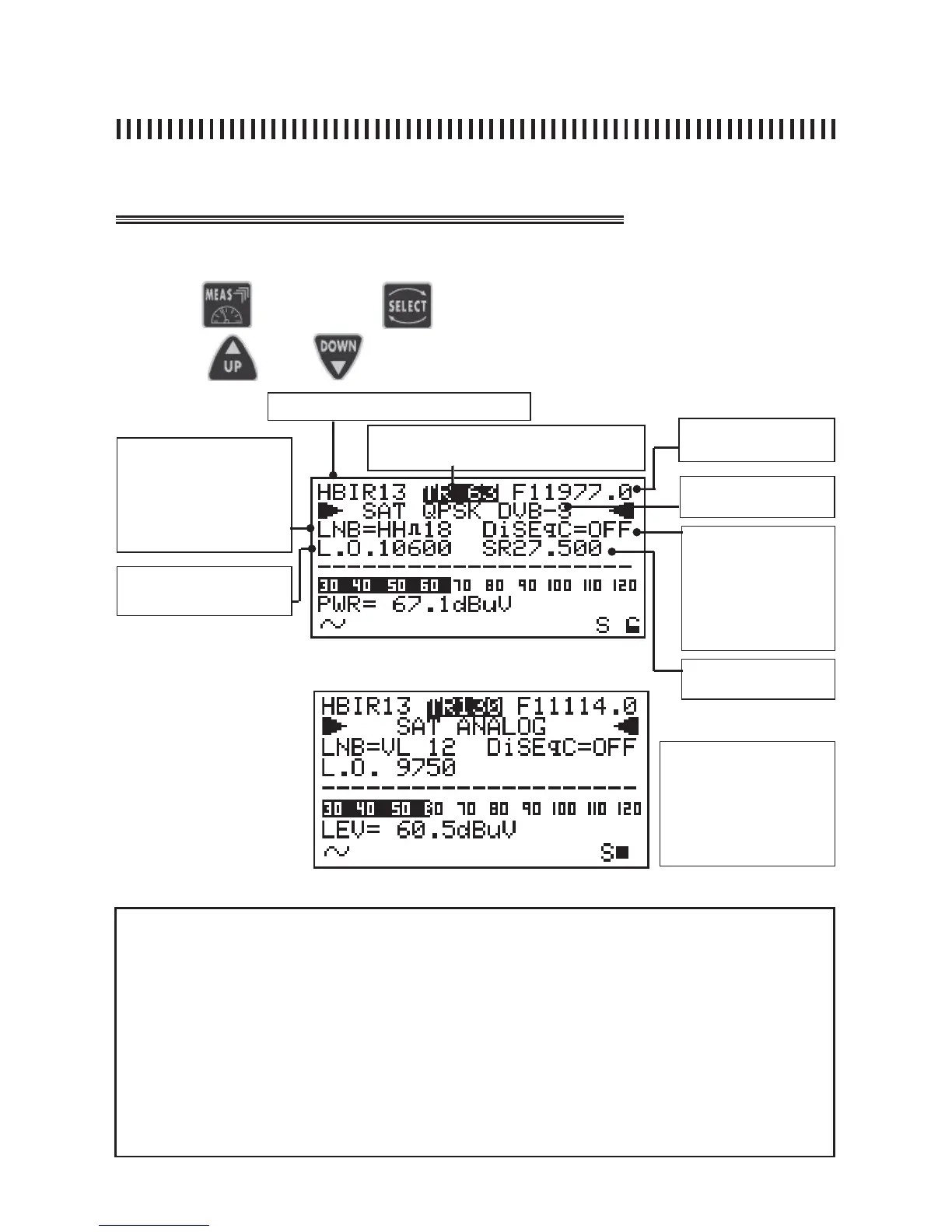
fi g. 15.1 Digital signal fi rst level measurements.
Press the
and use the
key to choose the fi eld to be modifi ed
use keys and to modify the displayed value.
15.1 Power measurement (digital) or Level measurement (analogue)
Memory Plan (Ref. Sec. 11.0)
Transponder Frequency
MW o IF
Active Memory Plan transponder or pro-
gramme number (Ref. Sec. 11.0)
Modulation: analogue
or Digital QPSK
LNB
LINE FEED
• Vertical low: VL 12
• Vertical high: VH 12
• Horizont low: HL 12
• Horizontal high: HH 12
• OFF
D
ISEqC:
• Position A
• Position B
• Position C
• Position D
• OFF
Local oscillator: from 0 to
20.000 MHz
Symbol Rate: from 2 to
45 MS/s
NOTES
• If there is no signal or if the signal level is below the meter’s measurement dynamic range, the
string PWR_TOO_LOW (power too low) will be shown,
• The meter will always show a graphic bar proportional to the signal level or power measurement,
• The graphic bar memorizes the peak signal level or power value this is represented by a vertical
line on the display,
• To display all the signal available measurements, the MEAS key has to be pressed repeatedly
(see next paragraphs in this section for more details),
• Regardless of the measurement level the meter is, by pressing the “Power On” key [14], meter will
return to the First Level or Power measurements display (Ref. fi g. 15.1 or 15.2) depending on the
type of transponder being measured (Digital or Analogue).
fi g. 15.2 Analogue signal fi rst level measurements.
THERE ARE 7 MODIFIABLE FIELDS
IN THIS MEASUREMENT LEVEL:
TRANSPONDER, FREQUENCY,
MODULATION, LNB, DISEQC, L.O.
AND SYMBOL RATE. THIS ONLY
FOR THE USER DEFINED MEMORY
PLANS.