ROXELL - 009 - 2416
COMEO - INSTALLATION INSTRUCTIONS
III-7
ELECTRICITY .... WATCH OUT !
LEAVE CONNECTIONS TO THE SYSTEM TO A QUALIFIED ELECTRICIAN !
- Wire t he system with the utmost care and attention.
- Always provide a solid earthing.
- Check all connections before you switch on.
- Always follow the wiring diagrams included in the control panels.
- Compare setting of the motor protection with the data on the motor label.
- Motor protections are set at minimum by the manufacturer.
- If you do not use a Roxell control panel, make sure to provide the necessary motor protections.
- Compare motor label plate and motor connection with local voltage :
DANGER
3x240V
3x200V
3x380V+N
3x415V+N
3x220V
(IEC38-3x400V+N)
(IEC38-3x230V)
MAXIMUM CABLE L ENGTHS TO THE MOTORS: SEE PAGE III-60
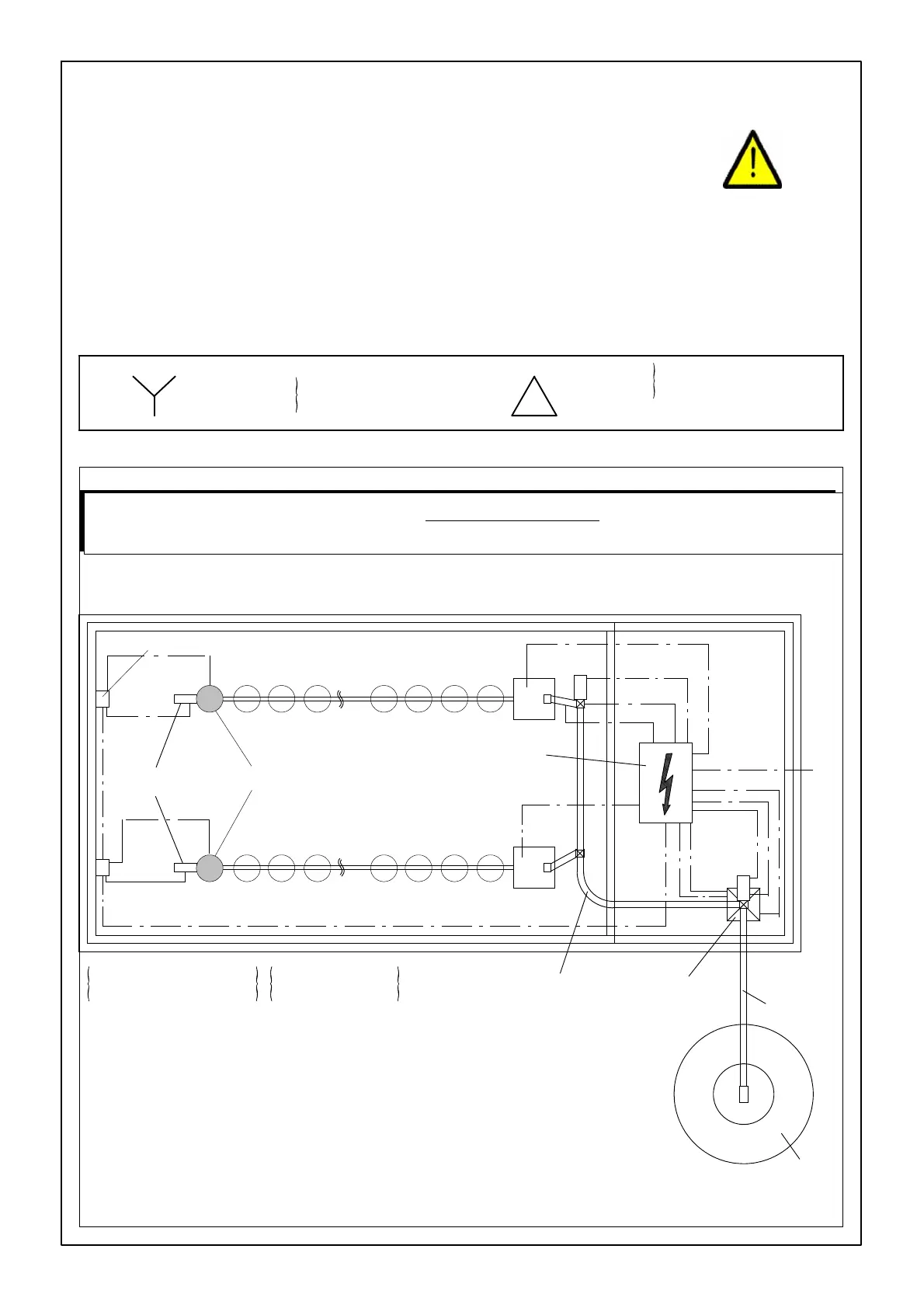
FIGURE 1.
FA
II
FA I
1
2
2
9
3
3
4
5
6
(3x380V+N / 3x415V+N
(3x400V+N IEC 38
3x200V / 3x220V
3x230V IEC 38
/3x240V).
Control unit
7
8
7
3
8
8
1. Supply cable(4x2,5+2,5).
2. Cable Flex-Auger power units (3x2,5+2,5).
3. Cable power units (3x2,5+2,5).
4. Cable max. sensor weigher (4x1,5)+ safety switch FA II (2x1,5).
5. Cable impulse switch weigher (2x0,75+0,75).
6. Cable safety switch Flex-Auger I(2x1,5)
7. Cable sensor control unit (2x1,5).
8. Cable min. switch hopper (2x1,5)+ safety switch +
9. Cablemax.sensor Flex-Auger (4x1,5).
10. Cable min. sensor weigher (4x1,5).
1
0
Central control panel
Weigher
Power unit
Bin
ONLY THE CONNECTION DIAGRAM IS SHOWN IN THE ASSEMBLY GUIDE. WIRING DIAGRAMS ARE
ALWAYS SUPPLIED WITH THE CONTROL PANELS.
SEALED PARTS IN CONTROL PANELS MUST UNDER NO CONDITION WHATSOEVER BE UNSEALED !
ELECTRICAL WIRING DIAGRAM
MOTOR STARTER