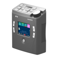
18 TR-825 Beltpack BTR-800, TR-800, TR-825
1. [MENU] and [SET] buttons – Used to select menus and
set options on the LCD.
2. LCD (Liquid Crystal Display)
3. [UP] and [DOWN] buttons – Used to select beltpack
options on the LCD.
4. Microphone Gain – Adjusts the headset’s microphone
gain. Adjust so that the BAT/OM LED will flash at the
beginning of most words at normal speech levels.
5. Push-to-Talk/Push-to-Transmit Switch –
Push-to-Talk (PT TALK) - The transmitter is always on. No
audio sen
t unless the talk switch, WTA, or SA button
pressed. Recommended position.
Push-to-Transmit (PT TX) –The transmitter and audio path
are of
f except when the talk swi
tch, WTA, or SA button is
pressed.
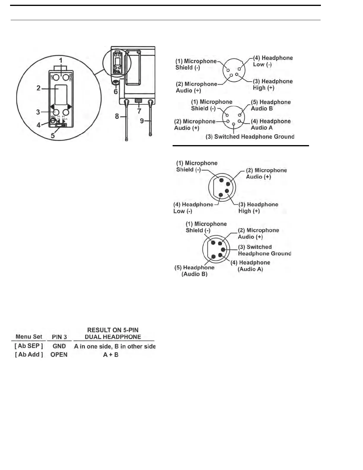
6. Headset Connector – Male XLR connector or female XLR
connector. A dynamic or electret headset microphone is
automatically detected by the beltpack and a bias voltage
supplied, if needed. Four-pin units are monaural. Five pin
units have a software setup which ground or opens pin 3.
Single-sided 5-pin headsets will only receive A or B, depending
on how headphone is wired. These headsets must have the
beltpack set for [Ab SEP]
7. Battery Latch – Press down to enable the battery pack to
be released. While the latch is held down, slide the battery
pack about 1/8-inch back, toward the latch, until it stops.
Then lift out.
8. Receive Antenna – Screw type 1/4-wave replaceable
antenna. The color dot on the screw end of the antenna must
match color dot on antenna receptacle.
9. Transmit Antenna – Screw type 1/4-wave replaceable
antenna. The color dot on the screw end of the antenna must
match color dot on antenna receptacle.
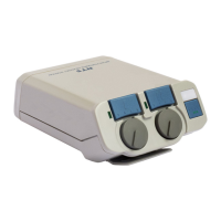
FIGURE 8.
TR-825 Rear Panel/Connector/Antennas
Male Connector
Female Connector
FIGURE 9.
Headset Jack Wiring