RDC6332G Control System User Manual
12
/
47
© 2015 Ruida Technology. All Rights Reserved
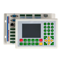
Chapter 4 Description of Controller Interface Signal
4.1 Interface of Main Power Source CN1
This control system employs single 24 power supply. For a certain
allowance, it is suggested to select 24V/2A power. Besides, this
system is compatible with 36V power, that is to say, the 36V power
of Motion driver can directly be connected to this main power port of
this system, but generally it is not suggested to do so.
4.2 Panel Power Interface CN0
CN0 only power for 320*240 TFT display, and can’t for other use.
Controller P+ connect to panel P+
,
Controller P- connect to panel P-.
4.3 Panel Signal-Cable Interface HDI
HDI is a normative DB15 interface, using the DB15 cable provided by factory to connect
the mainborad and the panel.
24V power positive (input)
Reserve for GND Or not used
5V power positive (output)
(
Only power for panel
)