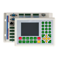
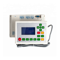
RDC6332G Control System User Manual
2 / 47
© 2015 Ruida Technology. All Rights Reserved
CONTENTS
Copyright Declaration...............................................................................4
Chapter 1 Overview...................................................................................5
1.1 Briefing................................................................................................................. 5
1.2 Description of Controller Model.......................................................................... 5
1.3 Comparison of Controller Performance................................................................6
Chapter 2 Installation Size....................................................................... 8
2.1 Installation Size of Controller...............................................................................8
2.2 Size of Panel......................................................................................................... 9
Chapter 3 Controller Pictures and Interfaces......................................10
3.1 Pictures of Controller..........................................................................................10
3.2 Pictures of Panel................................................................................................. 11
Chapter 4 Description of Controller Interface Signal.........................12
4.1 Interface of Main Power Source CN1................................................................ 12
4.2 Panel Power Interface CN0................................................................................ 12
4.3 Panel Signal-Cable Interface HDI...................................................................... 12
4.4 Reserved Interface HMI..................................................................................... 13
4.5 Udisk Interface....................................................................................................13
4.6 USB Interface..................................................................................................... 13
4.7 Ethernet Interface................................................................................................13
4.8 General Output Port CN2................................................................................... 14
4.9 3-axle Spacing and Special Input Interface CN3/CN4....................................... 15
4.10 X/Y/Z-axle Motion Drive Interface..................................................................16
4.11 Laser Power Control Interface CN6/CN7.........................................................17
4.12 Water Protect Input Interface CN5............................................................. 18
Chapter 5 Laser Power Interface Examples.........................................19
5.1 Digital Laser Power Supply of Glass Tube.........................................................19
5.2 Analog Laser Power Supply of Glass Tube........................................................ 19
5.3 RF CO2 Laser..................................................................................................... 20
Chapter 6 Step-servo Motor Driver Interface Examples....................21
6.1 Overview.............................................................................................................21