RDC6563F Standalone Fiber Cutting Control System User Manual V2.0 21
SHENZHEN RUIDA TECHNOLOGY CO., LTD
controller+5V power output,Current
output capability greater than 500mA
Servo drive enable signal
(output)
Servo alarm clear signal
(output)
Servo alarm signal(input)
controller+24V power output,Current
output capability more than 500mA
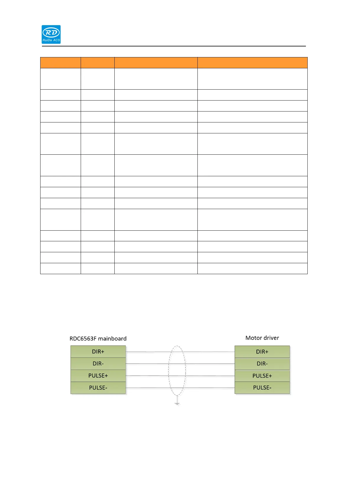
1) If connects stepper motor, the wiring method such as differential connection, common anode
connection, and common cathode connection can be used. The wiring method can be
determined according to the specific conditions of the stepper motor driver. It is
recommended to use the differential connection method.
Differential connection