RDC6563F Standalone Fiber Cutting Control System User Manual V2.0 31
SHENZHEN RUIDA TECHNOLOGY CO., LTD
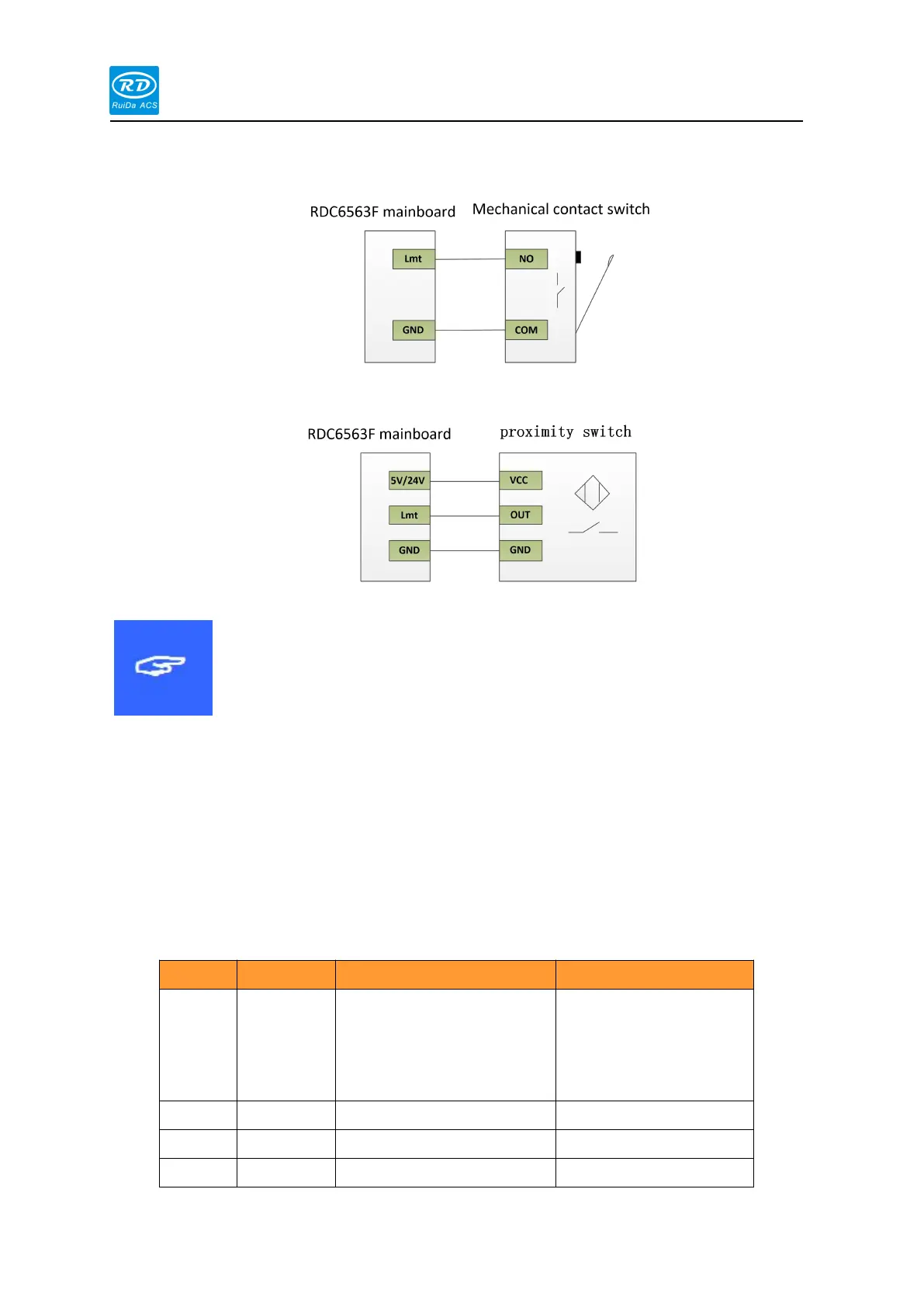
The typical connection of the mechanical contact switch is shown in the figure below:
The typical connection of the proximity switch is shown in the figure below:
When the Y-axis dual drive is enabled, the positive and negative
limit switches of the Y1 and Y2 axes must be installed, or the limit
switches of the Y1 and Y2 axes must be connected together. It is
not allowed to connect only Y1 axis or Y2 axis limit switch.
RDC6563F can support fiber lasers, CO2 lasers, RF tube lasers, etc., and is connected to
the laser through three rows of DB15. The LASER interface pin definitions are shown in the
following table:
controller +5V power
output, current output
capability is more than
500mA