6
INSTALLATION—SYSTEM INPUTS
SYSTEM INPUTS
The disconnect must be in the OFF posi-
tion and properly locked and tagged before
performing the following procedure.
Input terminals 1 through 28 support
+24 Vdc only. All remaining input terminals
are dedicated for specific devices. Con-
necting any other voltage or device other
than those intended may result in damage
to the control system.
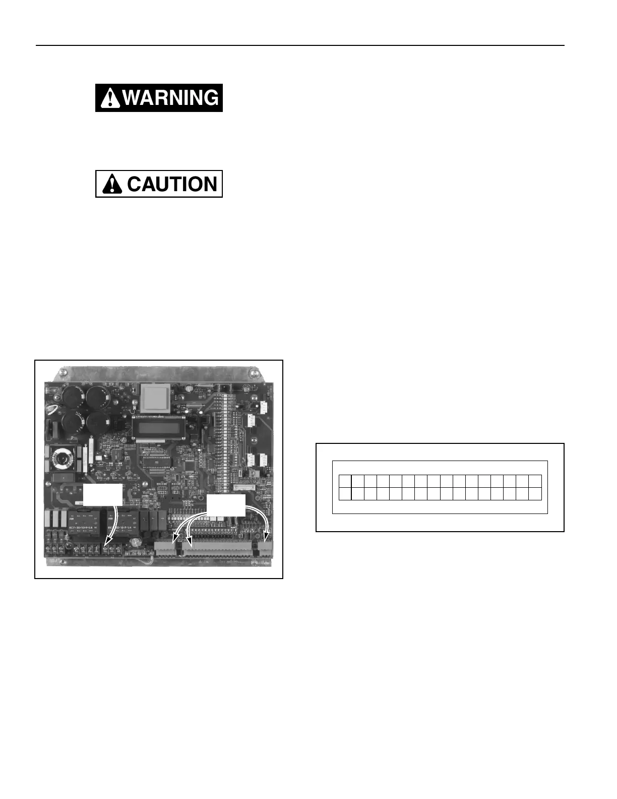
All connections (e.g., power supply lines, drive motor
control lines, encoder, activators, etc.) to the controller
are made by way of terminal screws and terminal
blocks. The screws and blocks are located along the
bottom edge of the control board. (See Figure 7.)
Figure 7
Power Supply Lines
Connect the power supply lines from the fused discon-
nect to the control panel as shown on the schematic that
was shipped with the door.
Motor
Connect the motor wires to the control panel as shown
on the schematic that was shipped with the door.
Motor Brake
Connect the motor brake to the control panel as shown
on the schematic that was shipped with the door.
Encoder
Connect the encoder to the control panel as shown on
the schematic that was shipped with the door.
External Emergency Stop Switches (N.C. Contacts)
E-STOP 1
Connect emergency stop switch E-Stop 1 to the control
panel (terminals 1 and 2) as shown on the schematic
that was shipped with the door.
If this input is disabled, the door will become disabled.
The controller will then display a corresponding emer-
gency stop message.
E-STOP 2
Connect emergency stop switch E-Stop 2 to the control
panel (terminals 3 and 4) as shown on the schematic
that was shipped with the door.
If this input is disabled, the door will become disabled.
The controller will then display a corresponding emer-
gency stop message.
Breakaway Bottom Bar (Input 1 — N.C. Contact)
Connect the breakaway bottom bar kill switch(es) to the
control panel (terminals 5 and 6) as shown on the sche-
matic that was shipped with the door.
If the bottom bar becomes disconnected from either
side column, a loss of this input will immediately stop
the door and “Door Ajar” will appear on the display.
(See Figure 8.)
Figure 8
NOTE: Later on with power applied, if you find it
necessary to reposition the bottom bar in
order to reattach it, the door can be jogged
up or down by pressing and holding the up
(
▲
) or down (
▼
) key. Once the bar is reat-
tached and the control system reset, the
up (
▲
), down (
▼
), and enter (
●
) keys will
automatically return to normal operation.
A5500006
Terminal
Blocks
Te r mi na l
Screws
0
Erro Jog
F06 rooarjA
rlynO
D