3
SYSTEM OVERVIEW—CONTROL PANEL
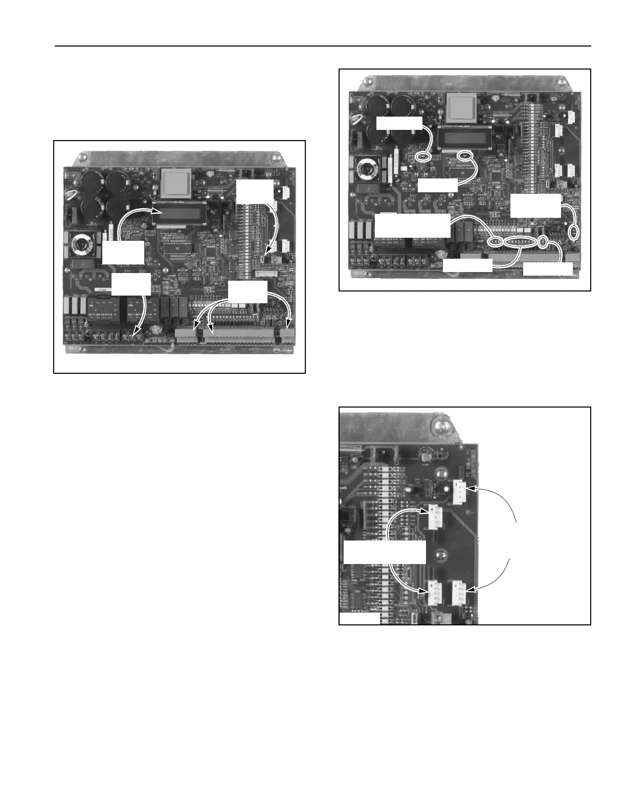
Controller
Located inside the control panel is the electronic con-
troller. The controller includes a two-line display, a ser-
vice switch, terminal blocks, and other miscellaneous
electrical components. (See Figure 2.)
Figure 2
TWO-LINE DISPLAY
All door commands and door status messages appear
on the two-line display. It also displays the cycle counter,
timer settings, alarm conditions, program settings, and
other miscellaneous messages.
The display is located near the top of the controller
(Figure 2) and can be viewed through the window on the
front of the control panel.
STATUS LEDS
Located on the electronic controller are various light-
emitting diodes (LEDs). These diodes are used for
in-depth troubleshooting. The LEDs indicate the operat-
ing status of the control system, the door, door activa-
tors, safety devices, and any other input devices
connected to the control system. (See Figure 3.)
Figure 3
PLUG-IN MODULES
For a door set up to be operated by a radio control or a
floor loop, a corresponding plug-in module for each type
of activator is required. The connectors for these mod-
ules are located in the upper right corner of the control
board. (See Figure 4.)
Figure 4
A5500006
Two-Line
Display
Terminal
Blocks
Service
Switch
Terminal
Screws
A5500006
Emergency
Stop Chain LEDs
Reversing
Edge LEDs
Run LED
Input LEDs
Power LED
LED U330
A5500006
Connectors
For Radio
Receiver Module
Connectors For
Floor Loop Module