10
SYSTEM STARTUP—INITIAL START-UP
INITIAL START-UP
System start-up is only to occur once the
door and control panel have been properly
installed, wired, and all preliminary door
adjustments made. Failure to follow the
instructions as outlined in the installation
manual that was provided with your door
can result in damage to the door upon ini-
tial system start-up.
1. Release the brake located on the end of the motor
and manually move the door to the half-open
position.
2. Apply power to the control system.
3. Check the motor rotation by pushing the up (
▲
) and
down (
▼
) keys briefly. The door should open with
the up (
▲
) key and close with the down (
▼
) key. If
the door does not operate in this manner, reverse
two of the motor wires (not the incoming three-
phase supply wires).
NOTE: Reversing the incoming supply voltage
lines will not solve the problem if the motor
is running in the wrong direction.
The door open and door close limits are to
be set only after verifying that the motor
(door) operates in the proper direction
when the up (
▲
) and down (
▼
) keys are
pressed.
4. Set the door open and close limits according to the
instructions shown on the controller display.
If the display shows error messages, some of the
required input connections may be missing. Once
the missing inputs are connected, the open and
close limit set-up should begin. Otherwise, refer to
“FAULT CODES” on page 26.
5. Set the open and close limits following the setup
procedure as described on the display.
NOTE: When establishing the open and close
limit positions for your particular door, refer
to the installation manual that came with
your door.
6. Set ACL1 and ACL2 timers as required. (See
“PARAMETERS” on page 15.)
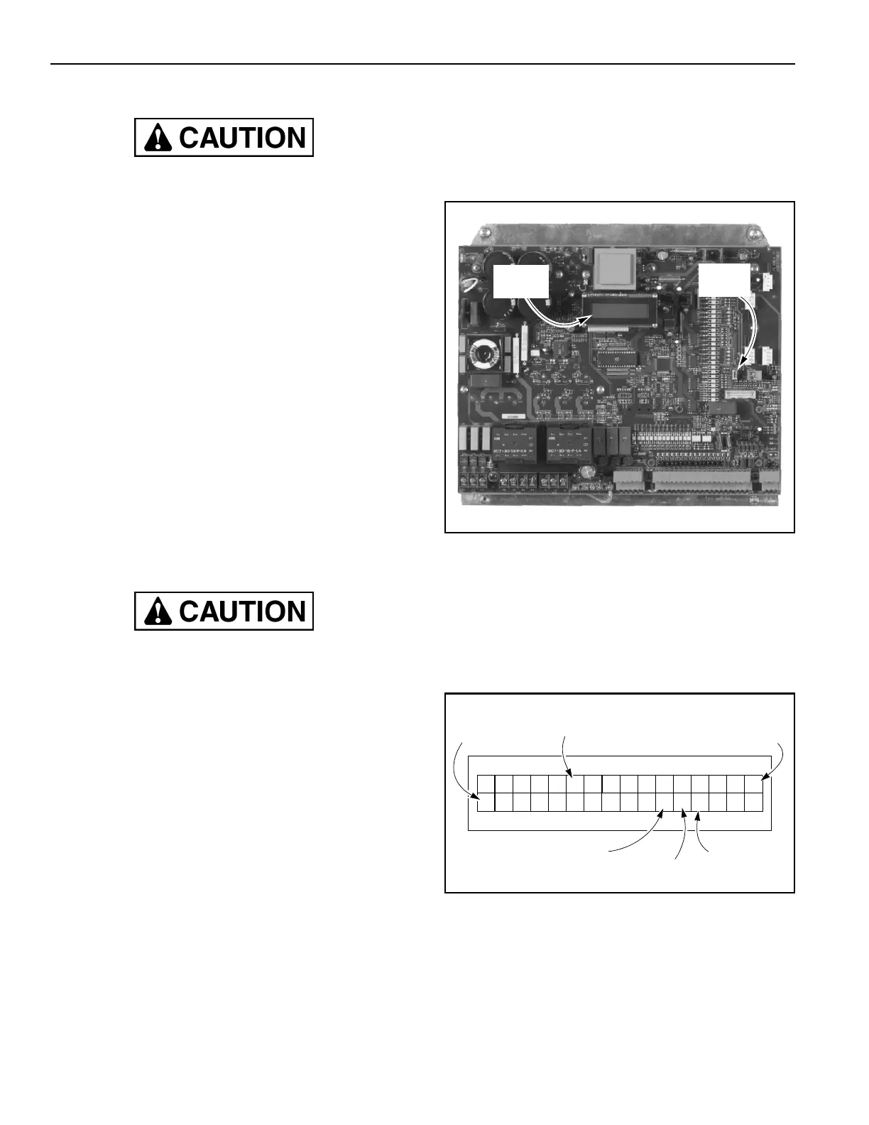
ACCESSING PARAMETERS
NOTE: To access operator level, service level 1,
or service level 2 parameters, the control
board service switch must be in the ON
position. (See Figure 9.)
Figure 9
Parameter Messages
A two-line display on the control panel (as shown in
Figure 9) displays all parameter settings when the con-
trol system is placed in a service level (operator level,
service level 1, or service level 2). Figure 10 details a
typical parameter.
Figure 10
For example, Figure 11 details door limit setup parame-
ter 210 (P.210).
A5500006
Two-Line
Display
Service
Switch
=
P:
Parameter
Value
Operator Level (O)
Service Level 1 (s)
Service Level 2 (S)
Parameter
Name or Group
Three-Digit
Parameter
Number
Parameter
Status
Unit