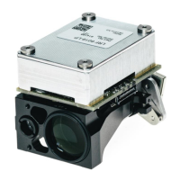
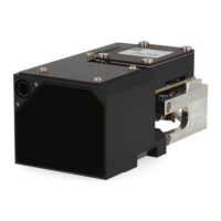
2 LRF Background Information
2.1 Rangefinder Principle “Pulsed LRF”
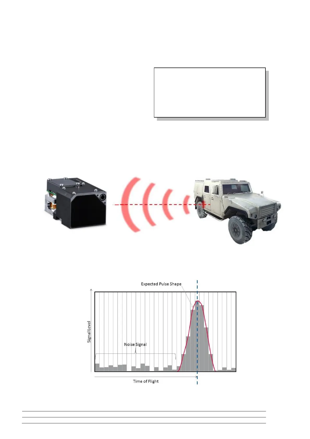
When the user triggers the laser rangefinder
measurement, the module sends a series of laser
pulses from the transmitter through the objective lens
to the target. For a good result, most of the laser
pulses have to hit the target.
If the user aims at the target, it will reflect a very small
percentage of the light back to the LRF module. The
module receives this remaining laser light by the
opposite objective lens, which focus it on the receiver diode.
Figure 4 below indicates how laser pulses are emitted from the transmitter, reflected at the target and
sampled by the receiver.
Figure 3: Pulsed LRF – Laser Pulses
The following Figure illustrates the sampled signal of the receiver diode. This information is used to calculate
the distance.
Figure 4: Sampled signal at the receiver diode
Measurement time (return flight) = 6.66 µs
Time of flight (one way) = 6.66 µs / 2 = 3.33 µs
Slope Distance r = light speed x time of flight
 Loading...