4 Mechanical Interface
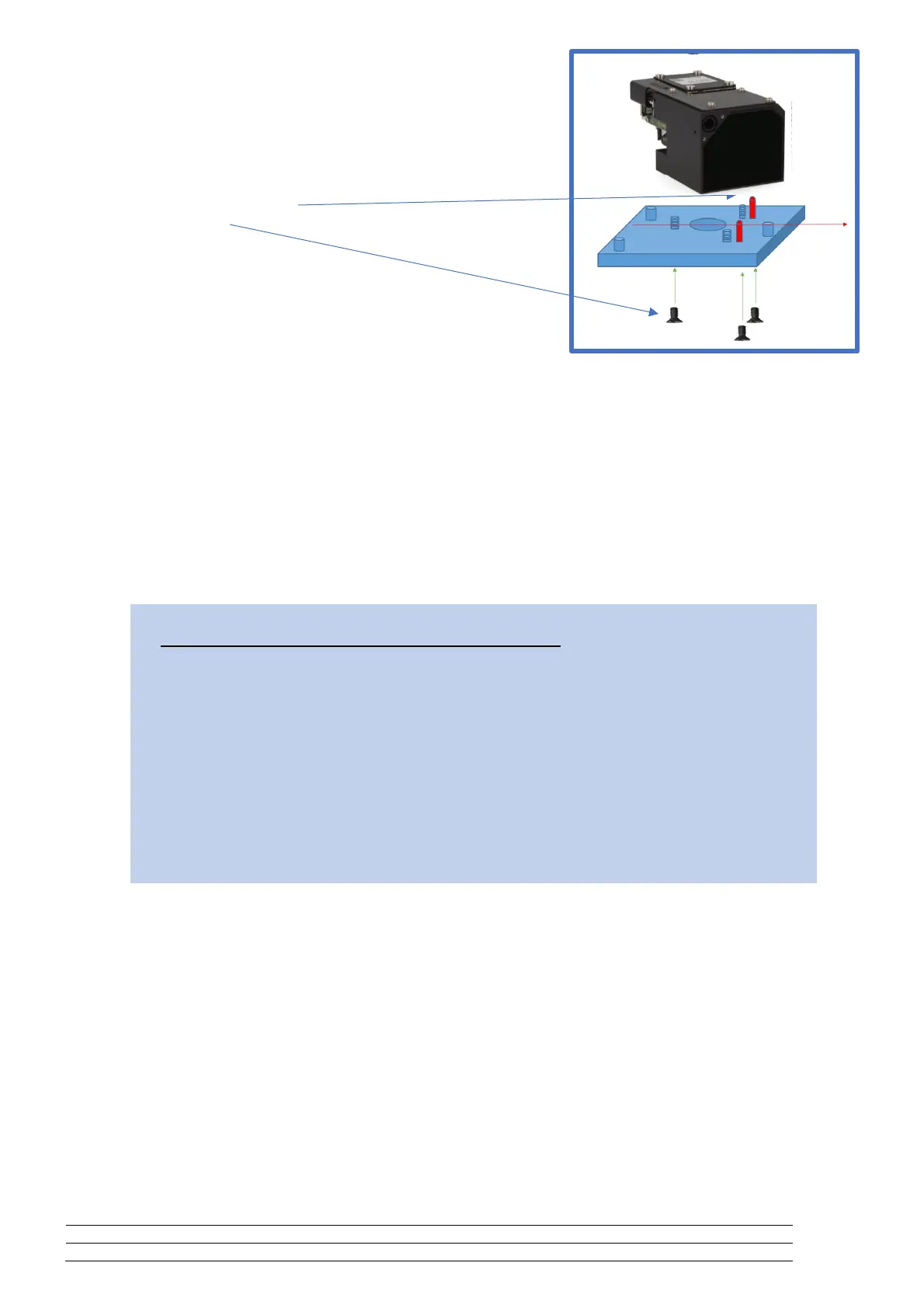
The LRF Module mechanical interface consists on:
Two positioning pin holes and
Three threaded holes.
4.1 Positioning pin holes
They define orthogonally the mechanical interface.
The emitted beam is aligned to them with a tolerance of ± 1.5 mrad.
The positioning pins provided in the host system must have a diameter of Ø2H6
4.2 Threaded holes
The module is secured by M5 screws and tightened with a torque between minimum 5 Nm and maximum 6
Nm.
4.3 Bench reference design
Drawings are in the appendix.
NOTICE
It is best practice and highly encouraged recommendation to:
Choose a highly stable material for the bench under thermal effects.
Provide a clean, flat and electrical conductive surface to provide a good contact to the module.
Observe ESD Electrical Static Discharge measures during the entire assembly of the sensor.
A defective design may originate:
Damage to the positioning pins affecting the mechanics integrity.
Electrical damage (short circuits and ground loops) if the contact surface is not appropriate.
Misalignment of the components due to mechanical-thermal stress.
 Loading...