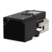
5 Optical interface
The LRF emits laser light from the transmitter lens of the following wavelengths:
1550 nm for range measurements
830 nm for pointer functionality (if selected)
To achieve optimal measurement results, the host system’s windows must allow optimal transmission of
both wavelengths.
NOTICE
To achieve optimal performance, is highly recommended to:
use two isolated optical channels separated from each other;
each of them with its own set of front windows;
use a tilt angle on the front windows of 5° - 10° from the plane perpendicular to the optical axis
the parallelism of both front windows (Tx, Rx) should be below 2 arcmin;
A defective design may lead to:
destruction of the module (ex. full laser energy is mirrored back by a perpendicular window);
incorrect or no measurements due to cross talk (scattered laser light from transmitter to
receiver)
reduction of performance with a non-optimal coating;
optical mirror effects (e.g. sunlight reflections to the target/enemy)
5.1 Coatings
The coating of the front windows should have the following specifications:
Measurement light: R < 0.5 % for λ = 1’500 ...1’600 nm, light angle 0°+/- 15° for both lenses.
Optional pointer light: R< 0.5 % for λ = 790…870 nm, light angle 0°+/-15° for transmitter lens.
5.2 Isolation of optical channels
The use of EPDM L 7510 material is recommended for optical isolation. This prevents cross talk (scattered
laser light from transmitter to receiver) In the appendix a reference design for such an optical isolation can be
found.
5.3 Environment
The LRF module is not gas tight. Therefore the LRF module in the host system requires a protective
environment with a window in front of the LRF module.
6 Hardware interface
6.1 Connector description
Power supply and communication between the LRF module and the host system is performed via the system
connector SAMTEC LSHM. It is a hermaphroditic board to board and board to cable design.
The following diagrams indicate the system connector’s pin out and the description of each signal.

 Loading...