8.4 Command Structure
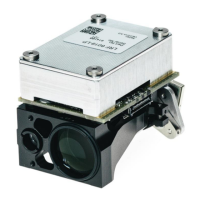
The figure below depicts the structure of the message frame. The message is an ASCII string. The ASCII
code used is UTF- 8 as shown in chapter 11.6 UTF-8 ASCII Table.
Figure 13: Message frame format
Example:
Host LRF Module
Command frame: >LM,Md,3*D5<0D>
LRF Module Host
Acknowledge frame: >AC*84<0D>
Response frame: >LM,Md,v0006091,R000E301,R000E301*46<0D>
Prompt: <
SOM (Start of Message) -> “>” (ASCII 0x3E) is used for message frame synchronization
Product ID -> for LRF modules is “LM”.
Message ID -> is composed of an upper case followed by a lower case letter “Md”
Parameters -> “3”
o if required, can be of different types (decimal, string, char in the range of 0x20 to 0x7E)
o Not allowed characters: 0x2A (‘*’), 0x2C (‘,’), 0x3E (‘>’), 0x3C (‘<’) and 0x21 (‘!’).
Checksum -> is the total sum in hexadecimal value of the message string between the ‘>’ and
the ‘*’ including the comas ‘,’
Table 1: Example of checksum calculation
EOM -> indicates the end of the message frame. <0D>.
Acknowledge -> indicates that the command is valid and the module is processing it.
>xx,<msg id>,<param 0>,....,<param N>*<chk sum><CR>
Checksum Range
EOM
Checksum
Message ID
SOM
Product ID
Parameter 0
Parameter N
 Loading...