SAGEM-LINK F 288055571-04
Installation and Operation Manual
Page 8/142
Issue 04 : July 2005
Reproduction and communication prohibited without the written permission of Sagem Communication
1.3 - IDU Installation
To install the IDU in a 19-inch rack :
• Attach the IDU in the 19-inch rack using four 6x12 stainless steel hex screws and washers into the
corresponding rack cage nuts. This attachment grounds the IDU to the earth.
Maint
Mux
Tribs
Cust
On
Off
Call
PC
POWER
EOW
Mgr 100bT
EastWest
TRIB 1-4 TRIB 5-8
TRIB 9-12 TRIB 13-16
ODU
POWER
Faston Male Plug
Figure 1.1 - IDU installation
• An additional grounding is possible by the use of a Faston plug (left side of the IDU). Use a 6
mm
2
section cable (minimum length required).
NOTE: When more than one IDU are to be mounted in the rack, it is recommended to keep a gap of 1
unit between two IDUs.
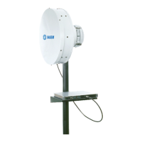
1.4 - Antenna Installation
Three types of antenna with several diameters are available for SAGEM LINK F radios.
• Integrated antenna with Sagem Link F ODU interface (0.3m, 0.6m, 0.9m, 1.2m or 1.8m
diameter). With these antennas, the ODU is directly attached on the antenna. In some protected
configuration using a coupler, the coupler is attached to the antenna, and the ODU are attached
on the coupler.
• External antenna with standard rectangular waveguide flange, which is connected to the
SAGEM LINK F ODU with a flex guide.
• External antenna with two access (dual polarized antenna) connected by two flex guides to the
ODUs.
Antennas models depend on the frequency bands :
• 7 GHz → 7.1 - 7.7 GHz
• 8 GHz → 8.025 - 8.5 GHz
• 13 GHz → 12.75 - 13.25 GHz
 Loading...