SAGEM-LINK F 288055571-04
Installation and Operation Manual
Page 16/142
Issue 04 : July 2005
Reproduction and communication prohibited without the written permission of Sagem Communication
Polarization setting is done by turning antenna source.
As coupler is not symmetrical in most cases, it is important to identify main position (lowest
insertion loss) and standby position.
It is also necessary to identify ODU cables (main or standby) with a label.
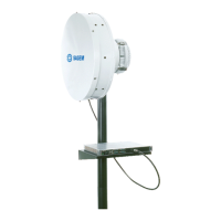
• 1+1 Frequency Diversity Configuration with Remote Mounts and a Dual Polarized Antenna :
In this configuration each ODU is remote mounted on a pole, and is connected to an antenna
access with a flex guide.
It is important to identify ODU cables for the one which is on vertical polarization (main), and the
one which is horizontal polarization (standby).
1.6 - Installing the IDU to ODU Coaxial Cable(s)
Recommended cables coaxial cables are Belden 9914 and Andrew LDF4-50A. If an other type of
cable is used, make sure it is compatible with outdoor use. This cable should be double or triple
shielded. Cable impedance is 50 Ohm, and is terminated by two N male connectors.
N connectors must be compatible with the cable, and connector mounting procedure must follow
connector manufacturer recommendations.
Install one cable in a 1+0 system or two cables in a 1+1 system.
It is very important to protect N connectors against water : wrap Isolation tape (15 cm) over the
coax cover. Start winding from coax cover with one half overlap with each winding in order to
protect completely connection from rain action. Press with fingers the tape and make sure the
protection is correct.
NOTE: Cables must be installed in compliance with national and local regulations and meet the
specific requirements of the installation site.
Some precautions are necessary when installing the equipment on unprotected places (e.g.,
antenna towers, building terraces, etc.) to prevent equipment from damage by lightning.
In a 1+1 system when two cables are installed, it is very important to identify main cable and
standby cable. If the cables are not labeled, it is necessary to perform a resistance check to
identify each cable.
Disconnect N connectors from IDU, and short circuit one of the N connector on the ODU side
(while the other one is open), and measure cable resistance on the IDU side. The lowest
resistance corresponds to the short circuited cable.
Put labels on both sides of the cables.
Remove the short circuit, make sure connectors are clean and dry, and connect proper cable to
each ODU.
Cable Grounding
It is necessary to ground properly ODU to IDU cable for a good lightning protection. For this
purpose, a cable grounding kit is provided as an option.
 Loading...