Traction transmission
Engine power is transmitted to the consecu-
tive work and drive pumps by means of a flexi
switch. From the pump to the hydraulic motor
of the gear box the power is transmitted by
means of liquid. The pump output is adjusted
steplessly using the drive pedal between posi-
tions 0 and +/- maximum.
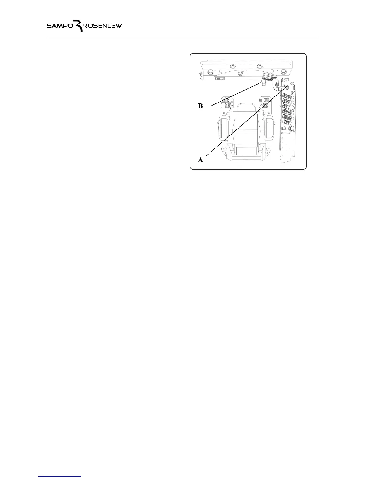
There are three gear speed ranges, which are
selected using lever A, fig. 13. The ranges are
intended for harvesting (range 1 with the gear
lever down pulled backward), driving in the
forest (range 2 with the gear lever up pushed
forward), and driving on the road (range 3 with
the gear lever down pushed forward). Gears
should be shifted on level ground without pres-
sing drive pedal B. From the gearbox power is
transmitted to the front wheels by means of
the drive shafts and the final drives.
The speed of the harvester is controlled by drive pedal B. When the pedal is not pressed, the
harvester is stationary if the gear is engaged and the engine running.
Driving direction (forward/backward) is chosen by switch close to left joystick (switch A, picture
13a). Drive direction forward is selected by pushing switch forward. Correspondingly drive direc
-
tion backwards is selected by pushing switch backwards. Speed is controlled by pedal. Also the
engine speed (r/min) and potentiometer B (fig 13a) near left joystick affect the speed.
When driving in traffic, the harvester head should be kept close to the harvester and tied. The
harvesting computer should be switched off in case of unintended crane movements.
A forest harvester equipped with hydrostatic transmission must never be parked using
only the gear, but the parking brake must always be engaged. The hydraulic motor
cannot keep the harvester stationary for a long period.
Four wheel drive
Rear-wheel drive is switched on electrically using switch N on the right-side instrument panel,
fig. 2. The coupling shall be done with the harvester stationary. 4WD is available on gears 1
and 2. When towing the harvester, four-wheel drive must be off and the engine running to allow
the wheel motors to be disengaged. Short-distance towing at a low speed is permitted if the
engine and the drive pump cannot be kept running.
Differential and rear- wheel drive lock
There are often situations when both the wheels on the front or rear axle do not have sufficient
grip in respect to the required traction power. In this case one of the wheels stops gripping,
which will further decrease the traction power. This can be avoided by engaging either the front
lock using switch P (fig. 2) and/or the 4WD lock using switch O, (fig. 2). The engagement of the
4WD lock generates anti-skid between the front and the rear. This also engages the hydrau-
lic lock between the rear wheels. The 4WD lock does not hold 100 %. Thus it allows different
wheels to turn at a different speed. On solid ground the 4WD lock makes turning difficult, so it
should be switched off. The mechanical differential lock at the front should also be disengaged
before sharp turns. The front mechanical lock can be switched on when the machine is stopped
and it can be used on gears 1 and 2. The four wheel drive lock is only available on gear 1.