EB 8384-2 EN 51
Mounting and start-up
5.4 Attachment according to
IEC60534-6
Î Requiredmountingpartsandaccesso-
ries:Table4onpage25.
Î Observetraveltablesonpage28.
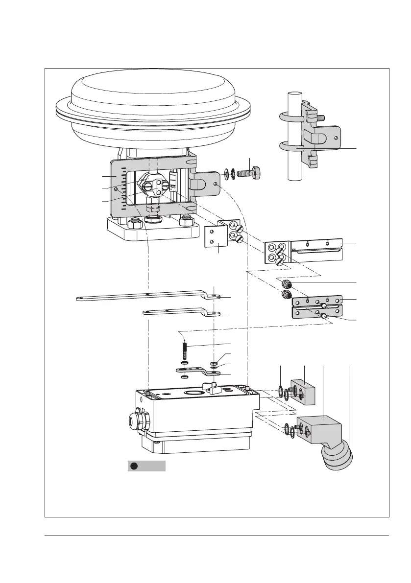
Î RefertoFig.8
The positioner is attached to the control valve
usingaNAMURbracket(10).
1. Screw the two bolts (14) to the bracket
(9.1) of the stem connector (9), place the
follower plate (3) on top and use the
screws (14.1) for fastening.
Actuator sizes 2800cm² and 1400cm²
with 120mm travel:
− For a travel of 60 mm or smaller,
screw the longer follower plate (3.1)
directly to the stem connector (9).
− Foratravelexceeding60mm,mount
thebracket(16)rstandthenthefol-
lower plate (3) to the bracket togeth-
er with the bolts (14) and screws
(14.1).
2. MountNAMURbracket(10)tothecon-
trol valve as follows:
− For attachment to the NAMUR rib,
use an M8 screw (11) and toothed
lock washer directly in the yoke hole.
− For attachment to valves with rod-
type yokes, use two U-bolts (15)
aroundtheyoke.AligntheNAMUR
bracket (10) according to the em-
bossed scale so that the follower
plate (3) is shifted by half the angle
rangetotheNAMURbracket(the
10
11
1
1
14.1
3
3.1
16
15
14
1
1.2
1.1
2
9.1
9
6.1 6 7 8
Attachment to rod-type yoke:
rodswith20to35mmdiameter
Attachment to
NAMURrib
Additional bracket for
actuatorswith2800cm²
andtravel≥60mm
XL and L lever
1 Lever
1.1 Nut
1.2 Disk spring
2 Follower pin
3 Follower plate
3.1 Follower plate
6 Connecting plate
6.1 Seals
7 Pressure gauge bracket
8 Pressure gauge
mounting kit
9 Stem connector
9.1 Bracket
10 NAMURbracket
11 Screw
14 Bolt
14.1 Screws
15 U-bolt
16 Bracket
NOTICE
!
Only use the connecting plate (6) included in the accessories to
connect supply and output.
Never screw threaded parts directly into housing.
Fig.8: Attachment according to IEC60534-6 (NAMUR)
 Loading...


