-15-
Mechanical Disassembly
Mechanical disassembly should be made following procedures in numerical
order.
Following steps show the basic procedures, therefore unnecessary step may
be ignored.
Caution:
The parts and screws should be placed exactly the same position as the origi-
nal otherwise it may cause loss of performance and product safety.
The wiring method of the leads and ferrite cores should be returned exactly
the same state as the original, otherwise it may cause lose of performance and
product safety.
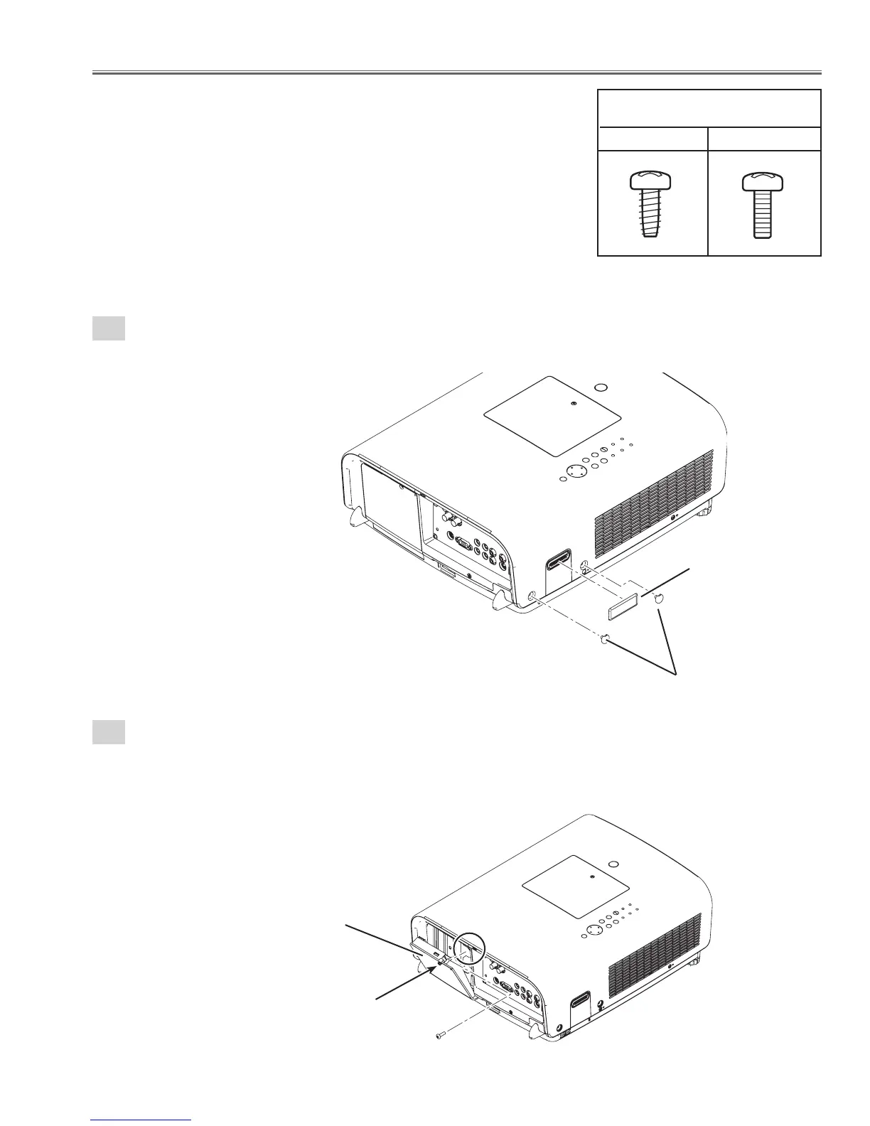
Screws Expression
(Type Diameter x Length) mm
T type M Type
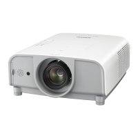
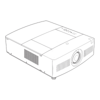
1-1
Cabinet top ass'y removal-1.
1. Remove 1 cover-A and 2 covers-B.
Fig. 1-1
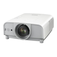
1-2
Cabinet top ass'y removal-2.
Cover-B
Cover-A
1. Loosen 1 screw-A(M3X11) and open the Lamp cover.
2.Remove 1 screw-B(M3X8).
A
Lamp cover
B
Fig. 1-2