-61-
Electrical Adjustment
1. Enter the service mode.
2. Receive the 16-step grey scale computer signal with
Input1 [RGB] mode.
3. Connect an oscilloscope to test point “TP35G” (+) and
chassis ground (-).
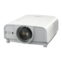
4. Select group no. “0”, item no. “3” and adjust the ampli-
tude “a” to be minimum by changing the Data value.
5. Connect an oscilloscope to test point “TP35R” (+) and
chassis ground (-).
6. Select group no. “0”, item no. “4” and adjust the ampli-
tude “a” to be minimum by changing the Data value.
7. Connect an oscilloscope to test point “TP35B” (+) and
chassis ground (-).
8. Select group no. “0”, item no. “5” and adjust the ampli-
tude “a” to be minimum by changing the Data value.
c PC-Gain adjustment
1. Enter the service mode.
2. Receive the 16-step grey scale computer signal with
Input1 [RGB] mode.
3. To start the auto-calibration for PC adjustment, select
group no. “260”, item no. “0” and then change data
value from “0” to “1”. After the auto-calbration com-
pleted, "OK" will appear on the screen.
c PC-Auto Calibration adjustment
1. Enter the service mode.
2. Receive the 16-step grey scale composite video sig-
nal with Input3 [Video] mode.
3. To start the auto-calibration for Video adjustment,
select group no. “260”, item no. “0” and then change
data value from “0” to “1”. After the auto-calbration
completed, "OK" will appear on the screen.
v Video-Auto Calibration adjustment
1. Enter the service mode.
2. Receive the 16-step grey scale 480i-component video
signal with Input2 [Component] mode.
3. To start the auto-calibration for 480i-component ad-
justment, select group no. “260”, item no. “0” and then
change data value from “0” to “1”. After the auto-cal-
bration completed, "OK" will appear on the screen.
b 480i-Auto Calibration adjustment
1. Enter the service mode.
2. Receive the 16-step grey scale computer signal with
Input1 [RGB] mode.
3. Connect an oscilloscope to test point “TP35G” (+) and
chassis ground (-).
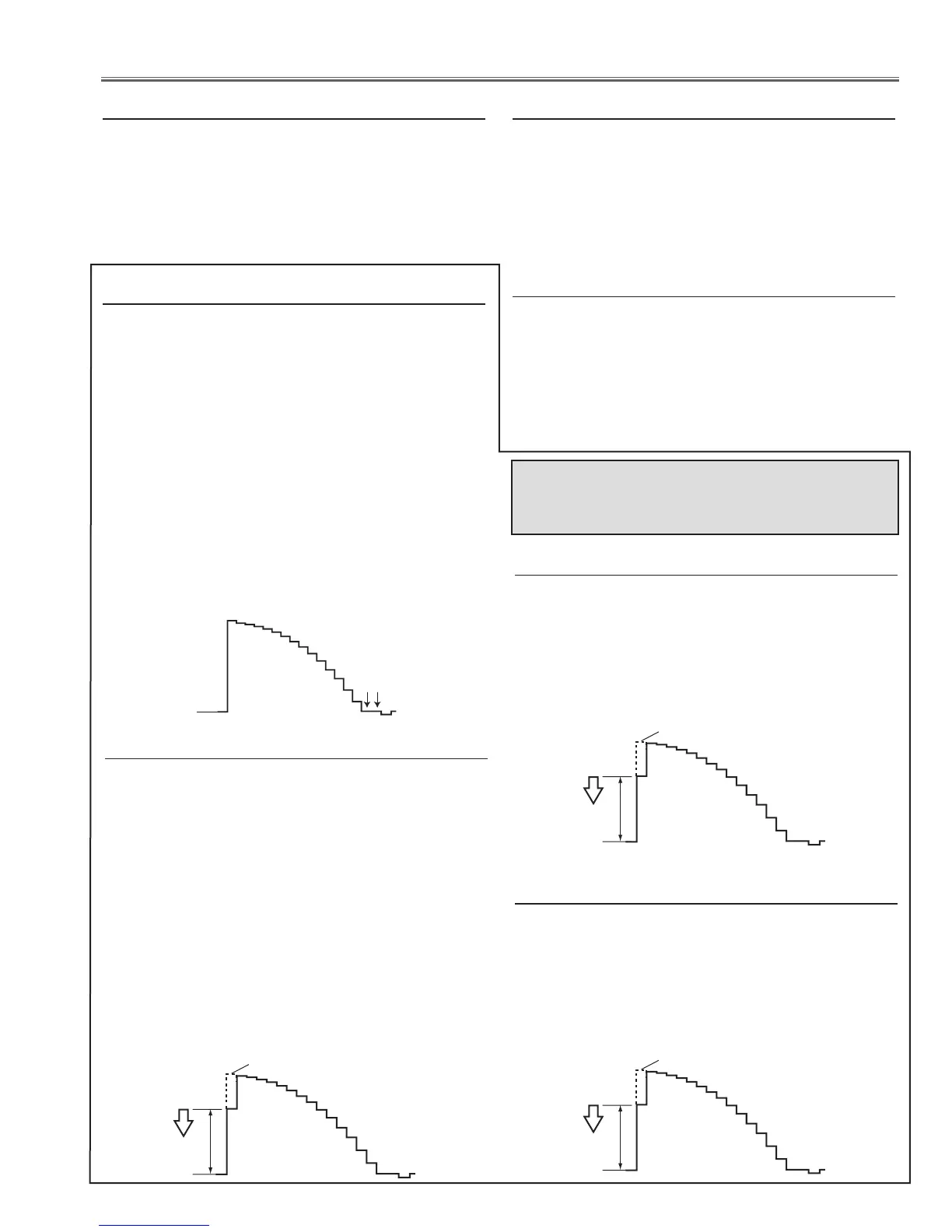
4. Select group no. “0”, item no. “0” and change data val-
ue to adjust the pedestal level and black level to be the
same level.
5. Connect an oscilloscope to test point “TP35R” (+) and
chassis ground (-).
6. Select item no. “1” and change data value to adjust the
pedestal level and black level to be the same level.
7. Connect an oscilloscope to test point “TP35B” (+) and
chassis ground (-).
8. Select item no. “2” and change data value to adjust the
pedestal level and black level to be the same level.
Pedestal Lebel
Black Lebel
c PC-Pedestal adjustment
1. Enter the service mode.
2. Receive the 16-step grey scale composite video signal
with Input3 [Video] mode.
3. Connect an oscilloscope to test point “TP35G” (+) and
chassis ground (-).
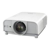
4. Select group no. “20”, item no. “2” and adjust the ampli-
tude “a” to be minimum by changing the Data value.
v Video-Gain adjustment
1. Enter the service mode.
2. Receive the 16-step grey scale 480i-component video
signal with Input2 [Component] mode.
3. Connect an oscilloscope to test point “TP35G” (+) and
chassis ground (-).
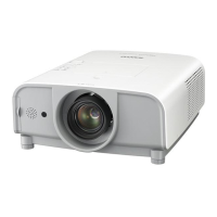
4. Select group no. “20”, item no. “0” and adjust the ampli-
tude “a” to be minimum by changing the Data value.
b 480i-Gain adjustment
Perform these manual adjustments instead of the
Auto-Calibration adjustment from [3] to [5] when
the auto-calibration is failed.