-15-
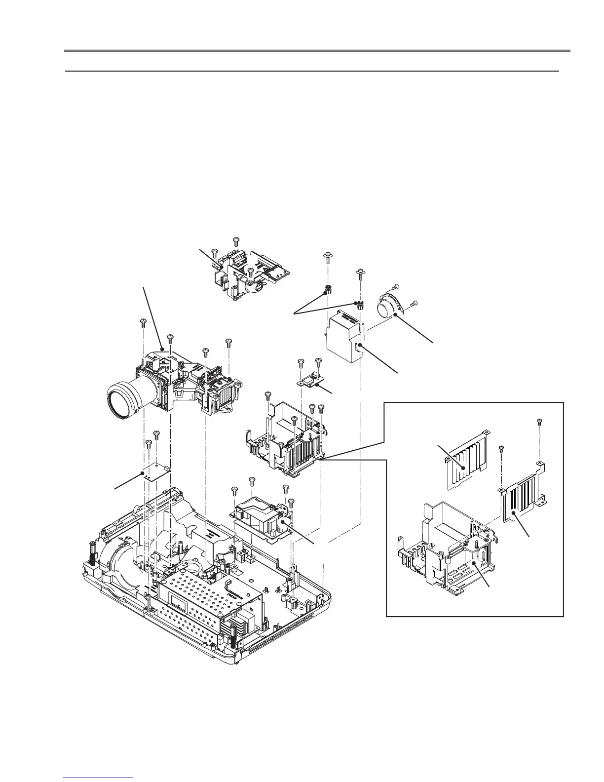
Mechanical Disassembly
1. Remove the 2 screws-A(T3x12) to remove the speaker holder.Remove the 2
screws-B(T3x8) to remove the speaker(SP901).
2. Loosen 3 screws-C to remove the Lamp assy (LP900).
3. Remove 4 screws-D (T3x8) to remove the Optical unit.
4. Remove 3 screws-E (T3x8) and 1 screw-F(M3x8) to remove the Lamp
holder. Remove 2 screws-G(T3x8) to remove the ID Connect board.
5. Remove 2 screws-H(T3x8) to remove the Sub Power board.
6. Remove 3 screws-K (M3x8) and 1 screw-J (T3x8) to remove the Filter board.
Fig.3
3. Speaker(SP901),Lamp assy(LP900), Optical Unit removal
Optical Unit
F
Lamp assy
(LP900)
C
ID Connect board
C
E
B
Speaker holder
B
Speaker
(SP901)
C
D
D
D
D
G
G
H
H
K
K
K
Sub Power
board
Filter board
Bushes
E
A
A
J
Inside light
shield
Outside
light shield
(T3x8)x2
E
Lamp
holder
 Loading...