-16-
Mechanical Disassembly
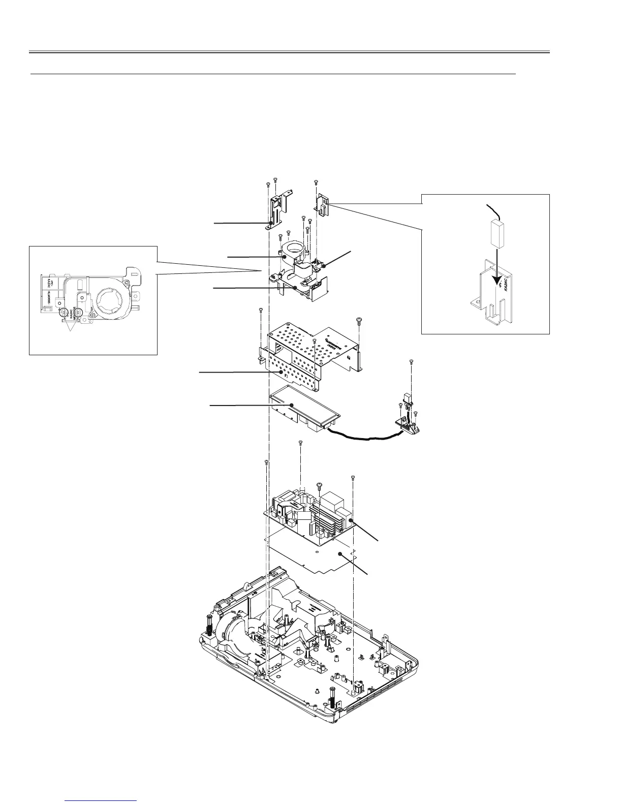
4. Fan (FN906) and Power Board removal
Fig.4
Power board
Ballast board
1. Remove 2 screws-A (T3x8) to remove the Cabinet front holder. Remove 1 screw-B (T3x8) to
remove the Sensor holder and Thermal Switch(SW902).
2. Remove 2 screws-C(T3x8) to remove the Lamp fan duct ass'y. Remove 2 screws-D (T3x12)
and 1 screw-E (T3x8) to remove the fan (FN906) and Lamp fan duct.
3. Remove 1 screw F (T3x8) and 2 screws-G (T3x8) to remove the Lamp Socket and Socket plug.
4. Remove 2 screws H (T3x8) and 1 screw-J (M3x8) to remove the Power board holder.
5. Remove 3 screws-K (T3x8) and 1 screw-L (M3x8) to remove the Power board.
B
A
D
H
Power board
holder
Power board
shield bottom
Cabinet front
holder
A
D
FN906
Lamp fan
holder
Lamp fan
duct
H
J
K
K
K
L
C
Lamp Socket
Socket plug
F
G
G
E
C
Sensor holder
SW902
Hooks
 Loading...