75
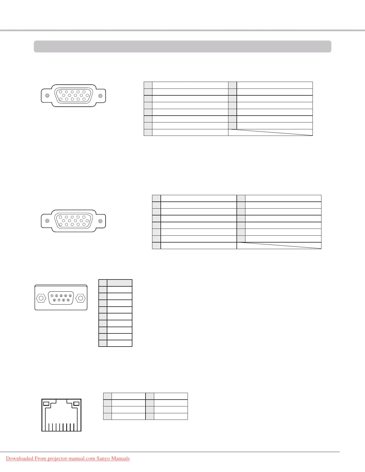
COMPUTER IN 1 /COMPONENT IN
Terminal: Analog RGB (Mini D-sub 15 pin)
Configurations of Terminals
Red (R/Cr) Input
Ground (Horiz.sync.)
Green (G/Y) Input
-----
Blue (B/Cb) Input
Ground (Red)
Ground (Green)
Ground (Blue)
1
5
2
4
3
6
7
8
+5V Power/-----
Horiz. sync. Input/Output (Composite H/V sync.)
Ground (Vert.sync.)
DDC Data
/-----
Ground/-----
Vert. sync.
DDC Clock
/-----
9
13
10
12
11
14
15
RX –
TX +
TX –
RX +
2
3
4
5
6
7
8
1
LAN TERMINAL
-----
-----
----------
CONTROL PORT CONNECTOR (D-sub 9 pin)
-----
R X D
T X D
-----
SG
-----
-----
-----
Serial
1
2
3
4
5
6
7
8
-----
9
COMPUTER IN 2/MONITOR OUT (ANALOG)
Terminal: Analog RGB (Mini D-sub 15 pin)
Red Input/Output
Ground (Horiz.sync.)
Green Input/Output
-----
Blue Input/Output
Ground (Red)
Ground (Green)
Ground (Blue)
1
5
2
4
3
6
7
8
-----
Horiz. sync. Input/Output
Ground (Vert.sync.)
-----
-----
Vert. sync.
-----
9
13
10
12
11
14
15
Appendix
Appendix
Downloaded From projector-manual.com Sanyo Manuals
 Loading...