RTC
®
4 PC Interface Board
Rev. 1.3 e
4 Principle Of Operation
20
innovators for industry
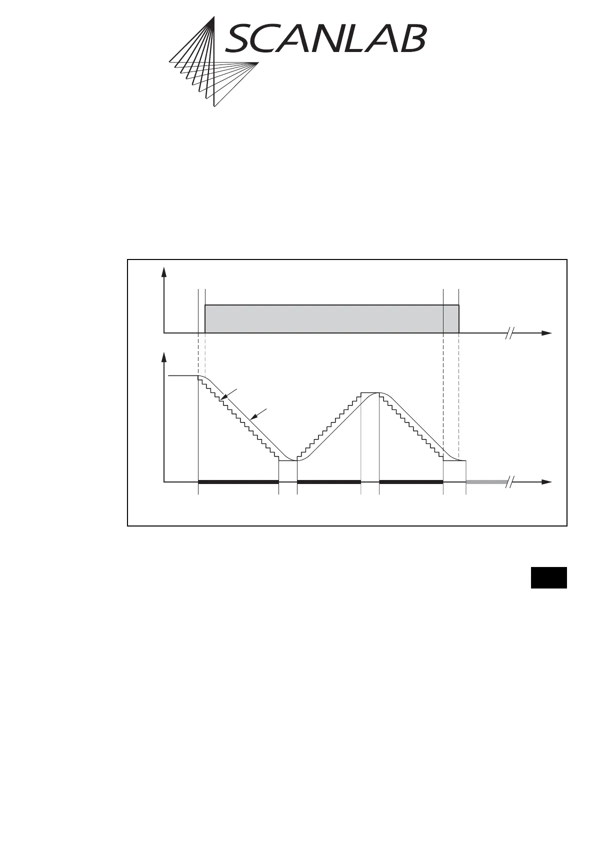
Polygon Delay
Between two successive mark or arc commands,
there is no need for a complete stop of the scanners.
Therefore the mark delay between two successive
mark or arc commands is replaced by a polygon delay
– see figure 8 on page 20.
The mark delay and the polygon delay can be set
independently
. In addition, the RTC
®
4 is able to vary
the length of the polygon delay, depending on the
angle between two marking vectors or the tangents
of the arcs. See the section "Variable Polygon Delay"
on page 21 for details.
…
Time
Laser
LaserOn
Delay
LaserOff
Delay
Polygon
Delay
Mark
Command
Mark
Command
Last Mark
Command
In This Polyline
Mark
Delay
Polygon
Delay
Jump
Command
etc.
Position
Set Position
Real Position
8
Scan head and laser control timing during a polyline with a constant polygon delay