RTC
®
4 PC Interface Board
Rev. 1.3 e
4 Principle Of Operation
21
innovators for industry
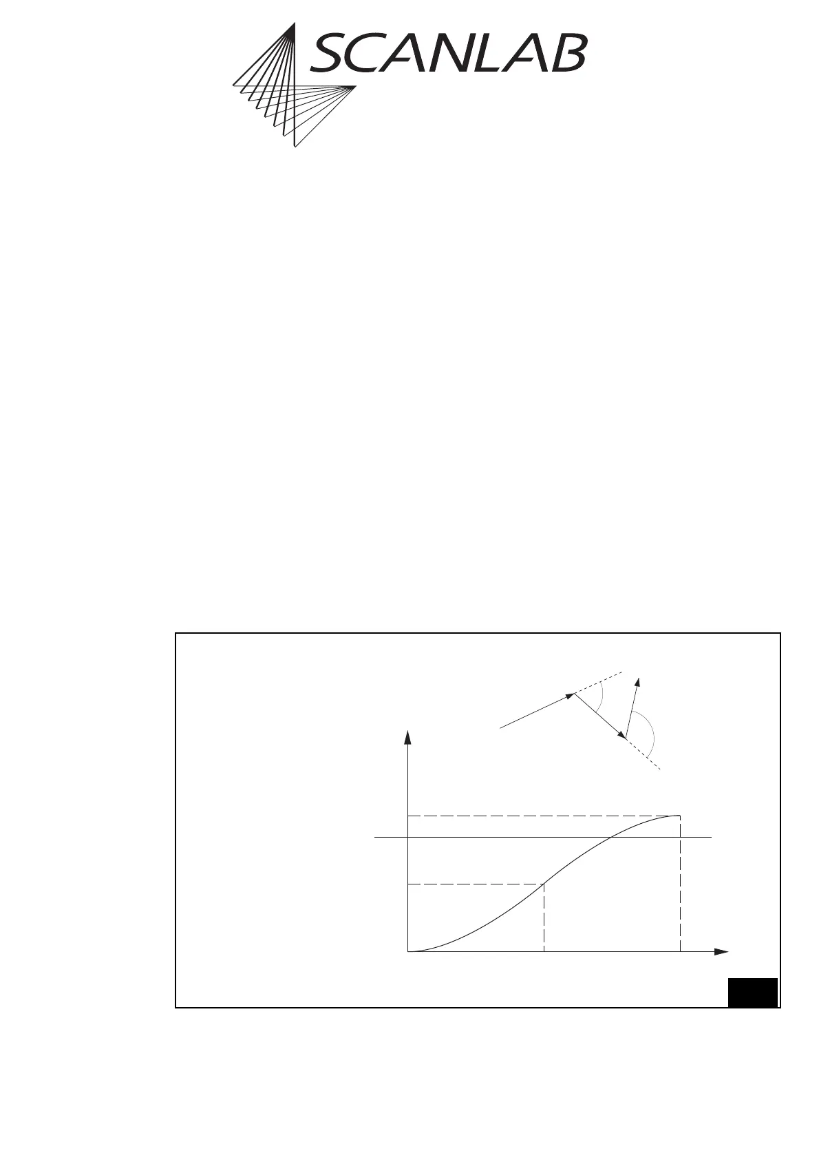
Variable Polygon Delay
A variable polygon delay mode can be activated via
the command set_delay_mode (page 104). In this
mode, the RTC
®
4 allows varying the length of the
polygon delay, depending on the angle φ between the
two successive marking vectors – see figure 9 on
page 21, below.
For each corner of the polyline, the RTC
®
4 calculates
the variable polygon delay v_delay(φ) as follows:
v_delay(φ)=scale(φ)
· polygon_delay,
where scale(φ) is a scaling function (0 ≤scale(φ) ≤2).
The parameter polygon_delay is set by the command
set_scanner_delays.
Figure 9 (bottom) shows the default scaling function.
This standard curve can be replaced by a customized
curve. See "Customizing The Variable Polygon Delay"
on page 23.
Edgelevel
Figure 9 shows that the variable polygon delay
becomes quite long if the angle φ is close to 180°.
This might lead to burn-in effects in the sharp corners
of the polyline. To avoid this, the user can define a
so-called edgelevel: If the polygon delay between
two mark or arc commands is longer than or equal to
this value, the RTC
®
4 turns the laser off after the first
mark or arc command – after inserting a LaserOff
delay – and starts a new polyline at the beginning of
the next mark or arc command. Also see figure 10 on
page 22.
For further details see set_delay_mode, page 104.
Edgelevel
Average delay, defined
by set_scanner_delays
Maximum
9
Variable Polygon Delay
Top: Definition of the angle φ
Bottom: Variation of the polygon delay (default curve)
f
2
f
1
ff
180°90°0°
0
scale(f)
1
2
1 – cos(f)
Angle φ between the
vectors of a
polygon