ScanMegInc. ModuleSIM‐P
UserManual 5 Version1.3
Introduction
The use of a SIM‐P module changes a simple type P photocell that has a detection feature into a
completescannerwithdifferentoutputs,andalsomaintainsallthefeaturesofaphotocell.Itislike
gettingasophisticatedphotocellandahigh‐techscanneratthesametime.
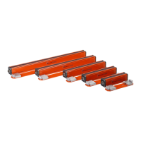
ThetypePsensorheadisanareaphotocellmadeupofanemitterandreceiver.Thesensordetects
objectsassmallas0.1inch(2.5mm).Theemitterandthereceivercanbe mountedupto100feet
(30m)apart.TheSIM‐Pmodulehasmultipleoutputs:aPNPcontact,
aNPNcontact,anRS‐232serial
communication port, an RS‐422 serial communi cation port and two analog 4‐20mA outputs.
Dimensionoftheobjectpresentinthefieldof viewanditspositionareavailablethroughtheanalog
andtheseriallinkoutputs.TheNPNandPNPoutputsare used
forthepresenceofanobject.The
modulealsohasamembrane keypad, a 32 alphanumeric display(2x16)andLEDto show different
status.
The head is a closed enclosure with a military, quick‐disconn ect connector.The rail‐mount SIM‐P
moduleissuppliedwiththeemitterandreceiver.All
parameterscanbedirectlyprogrammedwith
theSensorInterfaceModuleforPhotocell.Theemitterandthereceiveraredirectlyconnectedtothe
SIM‐P.
A32‐character,alphanum ericdigitaldisplayshowseachparameterandavailableconfiguration.The
SIM‐Pisconfiguredusingan8‐keymembrane.Statusof
eachcellofthereceiver(blocked,cancelled;
notblocked)canbeseenonthereceiverheadthroughitswindow,orontheSIM‐Premotedisplay.
Connectionoftheemitterandreceiverissimpleusingfourcoloredwiresandeachcolorisidentified
directlyontheterminal’sconnectorlocatedonthe
SIM‐P.Twoterminalsarepresent,one forthe
receiver and one for the emitter.These connectors are not dedicated as they can either accept
emitterorreceiver.Theonlyrestrictionistohaveanemitterunitandareceiverunitwiththesame
lengthconnectedtotheSIM‐P
.
Mechanical,electricalorinterconnectiondrawingsareavailableinAutoCADformat.Ifrequiredplease
contactourtechnicalsupportteam.