ScanMegInc. ModuleSIM‐P
UserManual 11 Version1.3
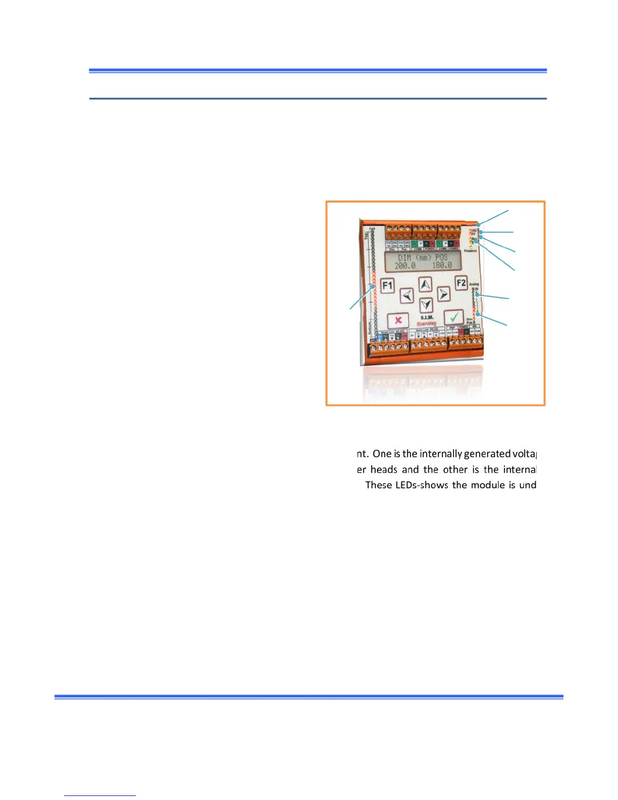
LED description
SomeLEDsarepresentontheSIM‐Pmoduleandalsoinsidetheemitterorthereceiverhead.Each
oneorgrouphasaspecificfunction.TheSIM‐Phasred,yellowandgreenLEDtohelpidentification.
BothreceiverandemitterheadsuseonlyredLEDs.
SIM‐Pmodule
1. LED Receiver Connected (Yellow)
When a valid receiver is recognized, this LED is
“on”.
2. LED Emitter Connected (Yellow)
When a valid emitter is recognized, this LED is
“on”.
3. Presence (Green)
Indicates the state of the detection.The LED
follows the output detection according to the
minimumdetectabledi mensionsetinthesystem.
4. Supply (Red)
Indicatesthestateofthepower
supply.TwoLEDs arepresent.Oneistheinternallygeneratedvoltage
(15 Volts dc) used to power the Emitter and the Receiver heads and the other is the internally
generated voltage (5Volts dc) used by theSIM‐Pmodule.These LEDs‐shows the moduleisunder
power.Forproperoperation,
bothLEDshavetobe“on”.
5. Analog output bar graph (Red)
Thisbargraphshowstheactualvalueofthedimensionorthepositionoftheobjectassentonthe
analogoutputs.At4mA,noLEDislight“on”.Assoonthatthevalueisgreaterthan 4mA,thefirst
LEDin
“on”.Atevery2mA,anewLEDisactivated(“on”),
6. Analog LED selection (Yellow)
IndicateswhichvaluebetweenthedimensionandthepositionareactuallyshownontheanalogLED
bargraph.WhentheDim.LEDis“on”,theanalogbar graphshowsthedimension. WhenthePos.is
“on”,thebargraph
showsthepositionoftheobject.
6
1
2
7
3
5
4