ScanMegInc. ModuleSIM‐P
UserManual 9 Version1.3
The electrical connections are very simpleto make.One canmake them withoutthe need of any
drawing.Oneachterminal,thecolorofeachwireisidentified.Justconnectthewiresattheposition
correspondingtotheircolor.Allwiresfromtheemitterhavetobeconnecte dtoeitherterminal
block
location;thenconnectthereceiver’swiresontheunused terminal.Visually,theconnectionswillbe
asshownontheright(bottomofthepreviouspage).
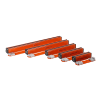
Photocelloutput
Whenapresenceisdetectedaccordingtothesetup(parameters),a
NPNandaPNPoutputareavailable.Bothareavailableatthesame
time.Theterminalsfortheconnectionarelocatedonthebottomof
themoduleontherightsideandareclearlyidentified.Eachofthem
hastwo
terminals:OUTandCOM.TheOUTterminalistheswitching
outputandtheCOMisthecommonreferenceforthePNPorNPN.
SerialLink
Twoseriallinksareavailable.OneisanRS‐232andthe otheris an
RS‐422link.Onlyonecanbeusedtotransmitthedimensionandthe
position.Nothing will be transmitted on the other serial link.The
selectionoftheactiveseriallinkismadewiththeparameter
ofthe
SIMmoduleandcanbedoneatanymoment.Pleasenotethatthe
RS‐422connectionandtheRS‐232connectionarenotlocatedonthe
sameterminalblock.
The RS‐232 terminal block is located on the bottom center of the
module.The0V,theRXand
TXarethethreeterm inalstobeused.
ThePNPINandthe+15Vterminalhavetostayunconnected.They
are used with a different type of sensor connected to the SIM
module.
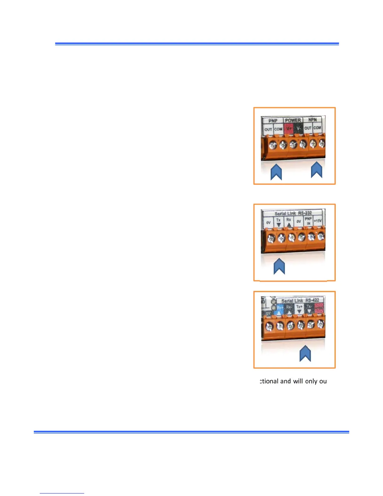
TheRS‐422 terminal block is locatedonthe botto mleftsideofthe
module.OnlytheTX
‐,TX+andthe0Varetobeconnected.Leavethe
otherunconnected.
RegardlessifyouhaveconnectedtheRx(RS‐232terminal)ortheRX+,
RX‐(RS‐422)accordingtothetypeofseriallink,themodulewillnever
check for incoming characters.Infact, boththe serial links
are unidirectional and willonly output
information(andnevercheckifacharacter is transmittedtothemodule).