ScanMegInc. ModuleSIM‐P
UserManual 8 Version1.3
SIM-P module connections
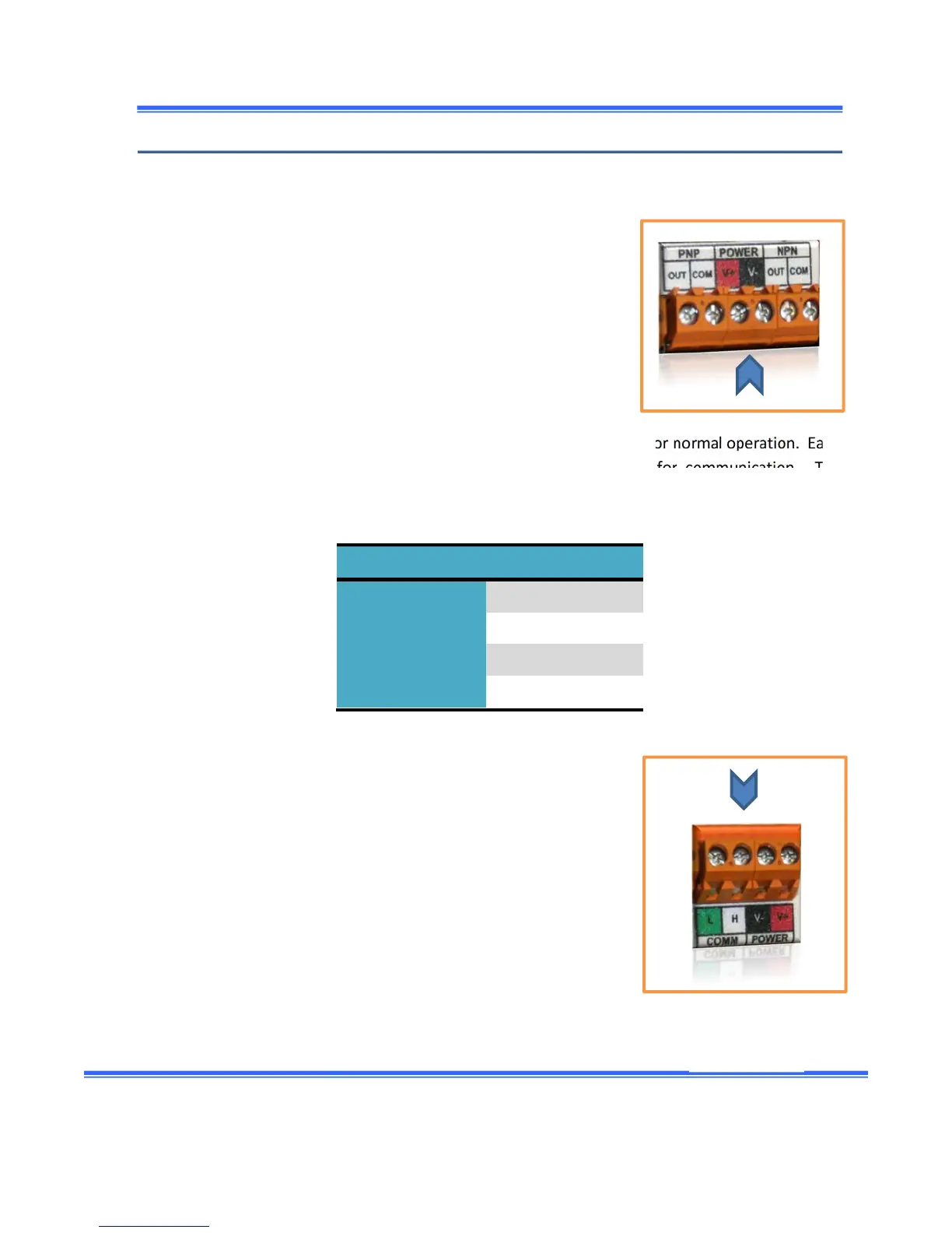
Powersupply
Another connection is the power.The terminals arelocated onthe
bottomrightofthemodule.ThePowerwordisvisiblywritteninfront
of the terminal.The red and the black color indicate respectively
positive (24Voltsdc) and negative terminals (0Vdc).A 24Vdc
Power
supplyisrequiredforthemoduleandissuppliedbythecustomer.This
supplyisdirectlyconnectedtothe SIM‐P.The15Vdcsupplyneeded
fortheemitterandreceiverismadeinternallybytheSIM‐Pmodule.
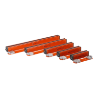
Headconnection
Theemitterandthereceiverhavetobecon nectedtotheSIM‐Pmodulefornormaloperation.Each
of them has a 4‐wire cable.Two wires are for power and two are for communication.The
communicationisCAN‐BUSlevel,butdoesnotsupporttheCAN‐BUSstandardprotocol.The
sensor
usesonlythehardwarefeaturesoftheCAN‐BUS.Thewirecolorsare:
Color Description
Red Power+15Vdc
Black Power0Vdc
White CANH
Green CANL
The emitter cable and receiver cable are connected to the terminal
located at the top right side of the SIM module, regardless of which
terminalisused.TheSIM‐Pmodulerecognizeswhichis connectedat
thefirstterminalblockandwhichisconnectedtotheother.Atpower
up,
the module communicates with the receiver and emitter and
determinesatwhichlocationeachisconnected. Onthe toprightside
ofthemodule,aLEDatRECpositionwilllightupifalinkisestablished
withthereceiver.AnotherLED atEMpositionwillalsolightupwhen
the link is established with the Emitter.For the system to work
correctly, one needs to connect one emitter and onereceiver of the
samesize.Ifitisnotthecase,anerrormessagewillbedisplayed.