Do you have a question about the ScanMeg SIM-P and is the answer not in the manual?
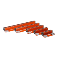
Details the power connection terminals and requirements for the module and sensor heads.
Explains how to connect the emitter and receiver using a 4-wire cable and identifies wire colors.
Lists and describes LEDs on the SIM-P module for status indication and output values.
Describes the power status LED located on the emitter head.
Describes the synchronization status LED on the emitter head.
Describes the power status LED located on the receiver head.
Describes the LEDs indicating presence detection on the receiver head.
Details LEDs showing the state of each individual cell within the receiver.
Details the functions of keypad buttons for menu navigation, parameter selection, and command validation.
Explains that emitter replacement is transparent and parameters are sent from the SIM-P.
Discusses receiver replacement and the need to update backup memory.
Details how to retrieve parameters from the receiver when replacing the SIM-P module.
Explains how to navigate through parameter menus using scroll buttons and their functions.
Allows setting multiple parameters simultaneously using seven pre-configured setups.
Identifies and cancels non-functioning cells, enabling the cancellation feature.
Clears the list of cancelled cells, making them available for detection again.
| Input Voltage | 24 VDC |
|---|---|
| Operating Temperature | -20°C to +60°C |
| Protection Class | IP20 |
| Category | Control Unit |
| Communication Interface | RS-485 |
| Weight | 0.2 kg |