13
2021-04-12 / V1.1
Contactors CP Series – Installation and Maintenance Instructions
Description
4
4
9
7
10
5
6
8
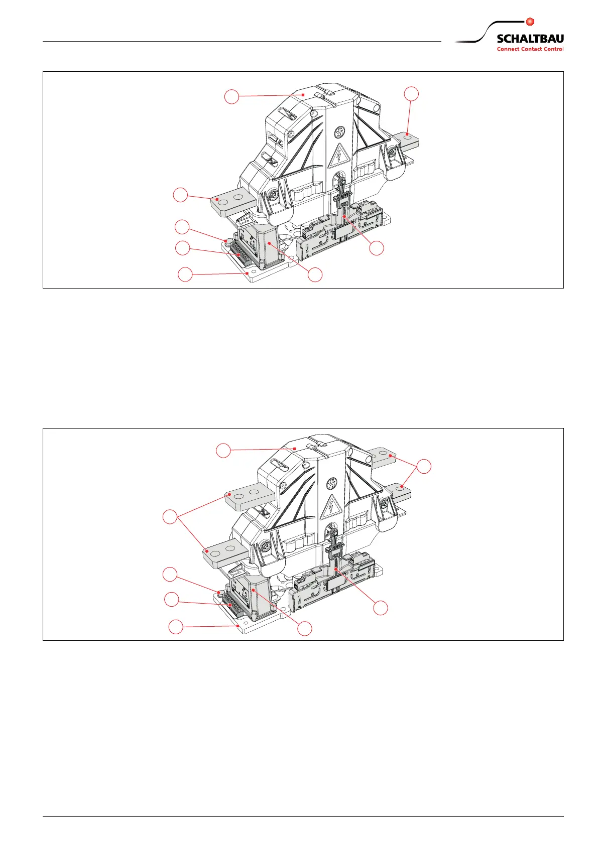
Fig. 5: CP series: Conguration example of NO and NC devices with load-free breaking capacity (no arc chamber)
4 Main contact terminals
5 Earth connection
6 Coil terminal (Wago 235)
7 Base plate
8 Economy circuit for coil
9 Auxiliary switch assembly (on both sides)
- 1x S870 (a1) + 1x S870 (b0) + 2x S826
- or 4x S826
- or high-voltage discharging contact
10 Cover (Inspection of main contacts is not required for
devices with load-free breaking capacity. The cover must
therefore not be removed.)
5
6
9
7
10
4
4
8
Fig. 6: CP series: Conguration example of CO devices with load-free breaking capacity (no arc chamber)
4 Main contact terminals
5 Earth connection
6 Coil terminal (Wago 235)
7 Base plate
8 Economy circuit for coil
9 Auxiliary switch assembly (on both sides)
- 1x S870 (a1) + 1x S870 (b0) + 2x S826
- or 4x S826
- or high-voltage discharging contact
10 Cover (Inspection of main contacts is not required for
devices with load-free breaking capacity. The cover must
therefore not be removed.)
 Loading...