33
2021-04-12 / V1.1
Contactors CP Series – Installation and Maintenance Instructions
Maintenance
9.3.3 Replacing the contact bridge
The contact bridge only needs to be replaced for devic-
es with arc chamber, but not for devices with load-free
breaking capacity. The cover of devices with load-free
breaking capacity must not be removed.
If the main contacts need to be replaced, allways re-
place all contacts (the moving bridge and the xed
contacts).
Safety
DANGER
Before beginning any work on the contac-
tors, make sure that
X
there is no voltage present,
X
all safety regulations are fully ob-
served.
X
Refer also to section „Dangers and
security measures“ on page 6.
Spare parts required
- Contact bridge assembly
See chapter „10. Spare parts“.
Tools required
- Torque wrench
Preliminaries
- The connecting cables or busbars of the main con-
tacts are disconnected, see “8.4.6 Connecting the
main contacts”.
- For contactors with arc chambers: The arc chamber
unit is removed, see “9.3.1 Replacing the complete
arc chamber unit”.
Removing the contact bridge
X
Unscrew the spring sleeve (1) by hand.
X
Remove the spring (2) and the spring support (3).
X
Remove the contact bridge (4).
X
Dispose of the old parts 1 to 4.
X
Continue with the replacement of the xed con-
tacts, see section “9.3.4 Replacing the xed con-
tacts”.
Installing the contact bridge
The new contact bridge assembly consists of spring
sleeve (1), spring (2), spring support (3) and contact
bridge (4). Use only the new parts 1 to 4.
X
Slide on the new contact bridge (4).
X
Attach the new spring support (3).
X
Insert the new spring (2) into the new spring sup-
port (3).
NC
1
2
3
4
5
1
2
3
4
3
Nm
3
Nm
5
NO
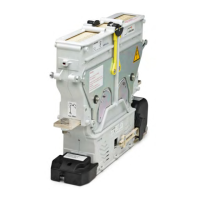
Fig. 32: NO/NC contactors with arc chambers – remove and
install the contact bridge
NO
NC
1
2
3
4
5
1
2
3
4
3
Nm
3
Nm
5
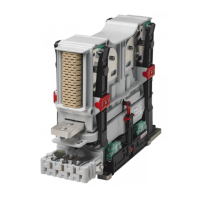
Fig. 33: NO/NC contactors with cover only – remove and in-
stall the contact bridge
 Loading...