12
2021-04-12 / V1.1
Description
Contactors CP Series – Installation and Maintenance Instructions
5.3 Conguration examples
2
3
1
2
3
4
5
6
4
9
7
8
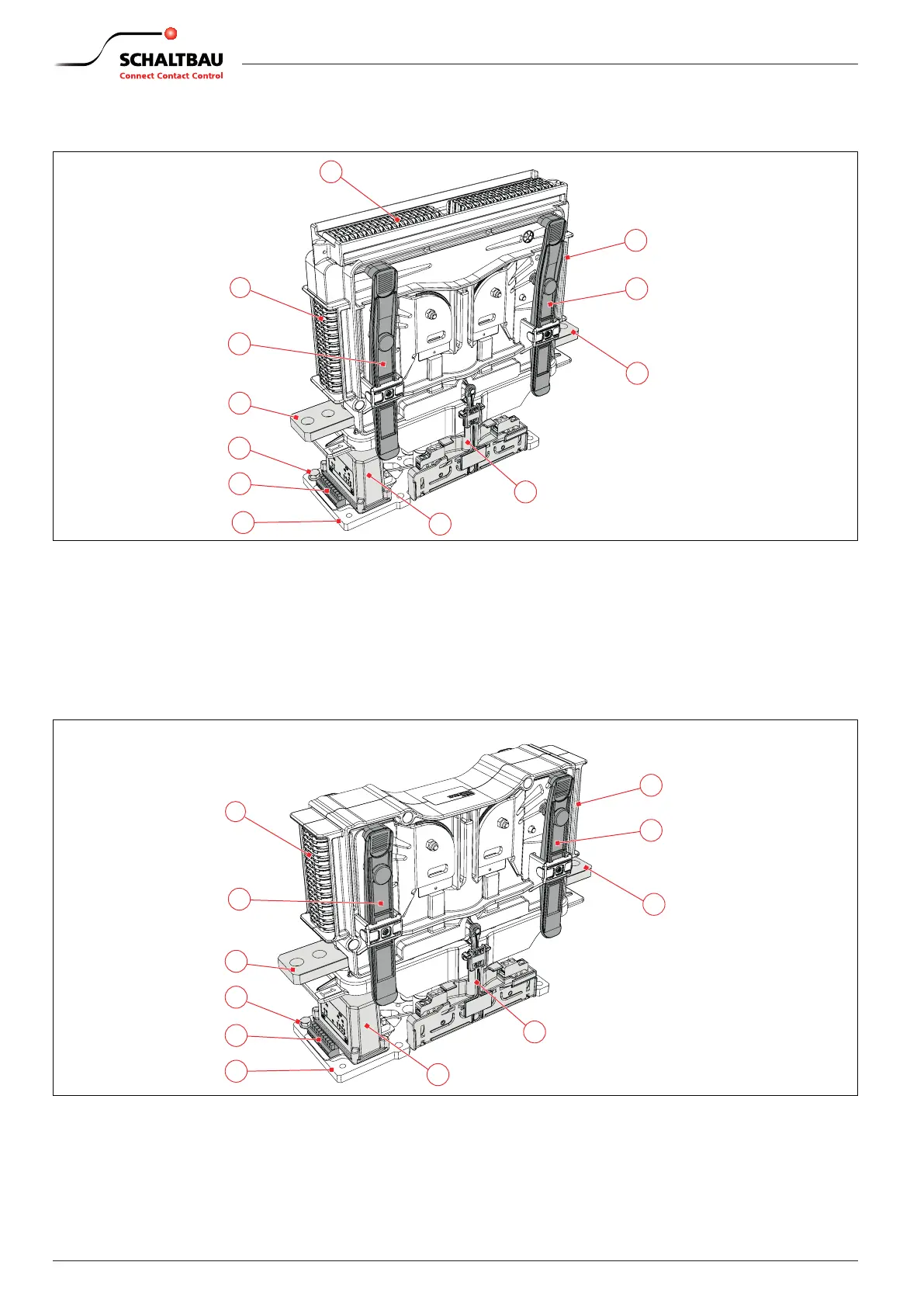
Fig. 3: CP series: Conguration example of NO and NC devices with high breaking capacity (large arc chamber)
1 Upper arc chamber area
2 Lateral arc chamber areas
3 Locking brackets 4x (to lock/unlock the complete arc
chamber)
4 Main contact terminals
5 Earth connection
6 Coil terminal (Wago 235)
7 Base plate
8 Economy circuit for coil
9 Auxiliary switch assembly (on both sides)
- 1x S870 (a1) + 1x S870 (b0) + 2x S826
- or 4x S826
- or high-voltage discharging contact
2
3
2
3
4
4
9
7
5
6
8
Fig. 4: CP series: Conguration example of NO and NC devices with medium breaking capacity (medium arc chamber)
2 Lateral arc chamber areas
3 Locking brackets 4x (to lock/unlock the complete arc
chamber)
4 Main contact terminal
5 Earth connection
6 Coil terminal (Wago 235)
7 Base plate
8 Economy circuit for coil
9 Auxiliary switch assembly (on both sides)
- 1x S870 (a1) + 1x S870 (b0) + 2x S826
- or 4x S826
- or high-voltage discharging contact
 Loading...