15
2021-04-12 / V1.1
Contactors CP Series – Installation and Maintenance Instructions
Installation
8. Installation
8.1 Mounting positions
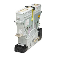
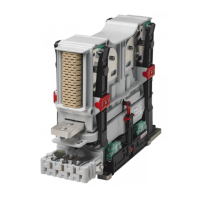
The contactors are designed for horizontal or vertical
mounting. Examples of permissible mounting positions
are presented in Fig. 7 and Fig. 8. Even mounting posi-
tions suspended over head are permitted.
Fig. 7: Examples of permissible mounting positions - NO/NC
devices
Fig. 8: Examples of permissible mounting positions - CO
devices
8.1.1 Dimensions/interfaces and further
technical specications
The dimensions and other technical specications are
given in the respective data sheets or can be found in
our C40 catalogue. The catalogue is available under:
https://www.schaltbau.com/en/media-library/
8.2 Mechanical installation
8.2.1 Preparatory measures
X
A suitable mounting frame or plate with 4 mount-
ing holes must be provided for fastening of the
contactor. See Fig. 9 and Fig. 10.
X
The mounting frame or plate must be solid enough
to carry the weight of the device under shock and
vibration conditions.
X
The mounting holes can be either:
- threaded holes (for threaded screws)
- or through holes (for threaded screws and nuts)
X
Fastening of the contactors on the mounting plate
is performed using four M8 mounting screws.
- The length of the mounting screws must be de-
termined dependent on the structural circum-
stances.
- To secure the mounting screws so that they
do not come loose, appropriate screw locking
elements must be provided. Schaltbau recom-
mends using Schnorr washers (or similar).
- The mounting screws (and if applicable the
nuts) must be strength class 8.8 or higher.
X
The mounting screws must be tightened to the
specied torque, which depends on the strength
class (min. 8.8) of the screws/nuts used.
 Loading...