19
2021-04-12 / V1.1
Contactors CP Series – Installation and Maintenance Instructions
Installation
8.3.2 Installation of the CPP with 600A
devices
Preparatory measures
X
With 600 A devices, 4 mounting holes at the
mounting frame or plate must be provided to fas-
ten the CPP.
X
The mounting holes can be either:
- threaded holes (for threaded screws)
- or through holes (for threaded screws and nuts)
X
Fastening of the CPP on the mounting frame or
plate is performed using four M5 mounting screws.
- The length of the mounting screws must be de-
termined dependent on the structural circum-
stances.
- To secure the mounting screws so that they
do not come loose, appropriate screw locking
elements must be provided. Schaltbau recom-
mends using Schnorr washers (or similar).
- The mounting screws (and if applicable the
nuts) must be strength class 8.8 or higher.
X
The mounting screws must be tightened to the
specied torque, which depends on the strength
class (min. 8.8) of the screws/nuts used.
[mm]
or M5 4 x Ø 6±0.1
51±0.1
111
±0.1
Fig. 16: Dimensions and arrangement of the mounting holes
for the CPP (not to scale)
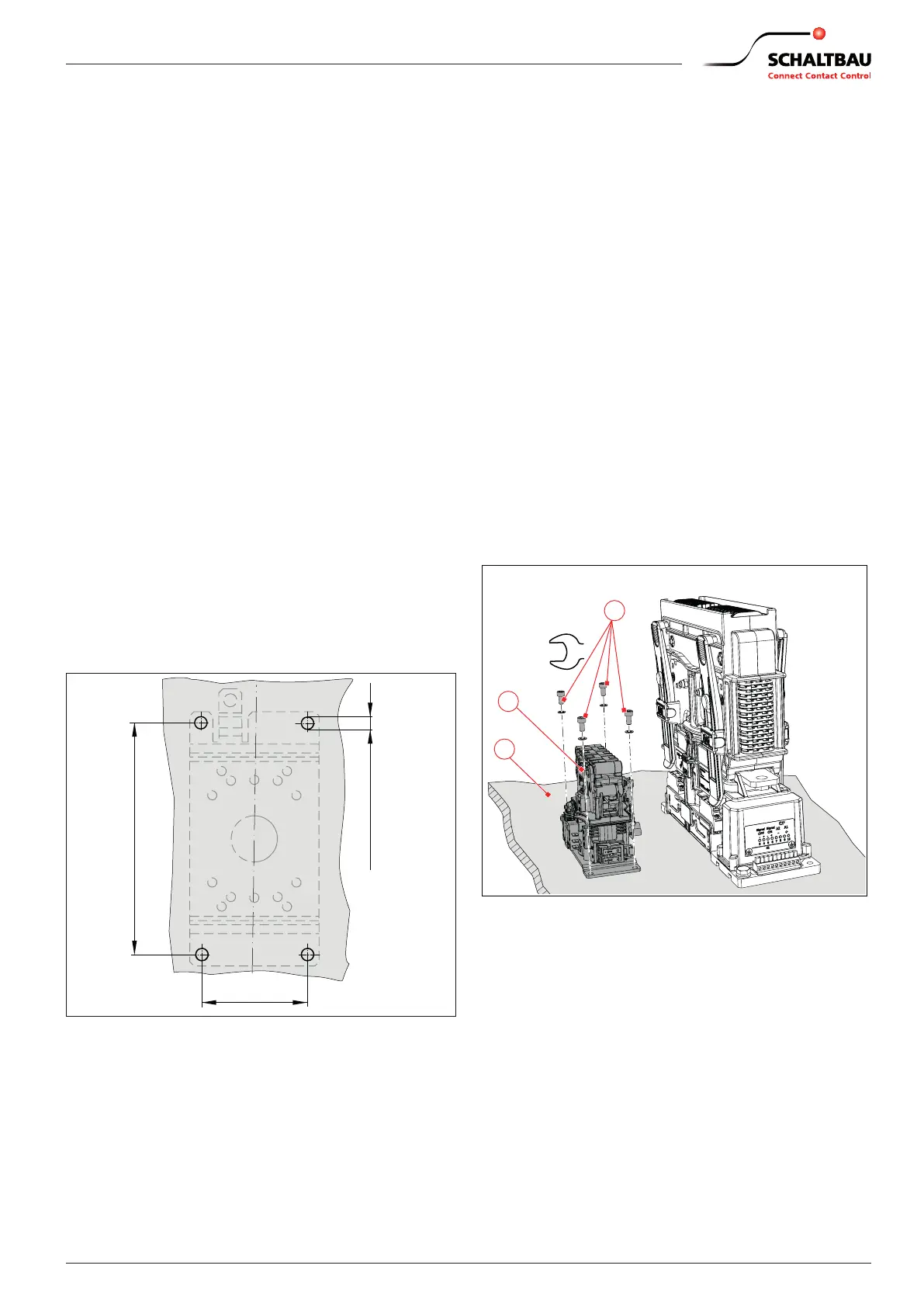
Installation procedure
X
Ensure that the contact surfaces on the mount-
ing plate (3) and the bottom of the CPP (1) are
free from dirt and other contamination (e.g. metal
chips).
X
Position the CPP (1) on the mounting plate (3)
which is provided with mounting holes.
X
Screw the CPP (1) on the mounting ange to the
mounting plate (3) using 4 mounting screws M5
including washers (2).
- In designs with the mounting holes imple-
mented as threaded holes, screw the mounting
screws into the holes directly, not forgetting the
washers.
- In designs with through holes, t the mounting
screws and washers and tighten the screws us-
ing suitable screw locking elements and nuts.
X
Tighten the mounting screws to the specied
torque, which depends on the strength class (min.
8.8) of the screws/nuts used.
3
2
Nm
1
Fig. 17: 600 A devices: Example for the installation of the CPP
at a separate mounting position next to the main
contactor
 Loading...