22
2021-04-12 / V1.1
Installation
Contactors CP Series – Installation and Maintenance Instructions
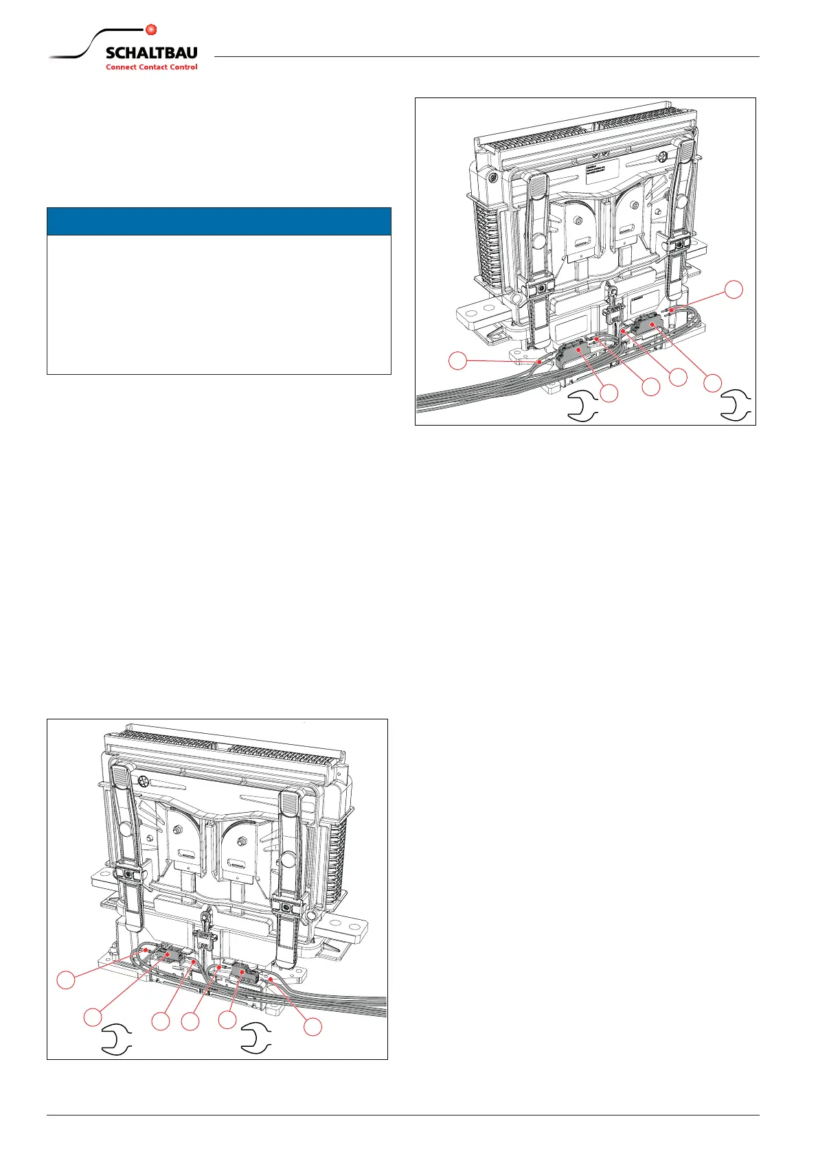
8.4.4 Connecting the auxiliary switches
The auxiliary switches (S870 and S826) are provided
with screw terminals (M3). The control wires for the aux-
iliary switches must be stripped accordingly (if neces-
sary, use appropriate wire end sleeves).
NOTICE
X
The maximum permissible conductor crosssec-
tion of the auxiliary switches control wires is
1mm
2
/ AWG 18 stranded wire.
X
Mechanically secure the control wires to mini-
mise feedback eects of forces caused by the
wires (e. g. shock, vibrations) acting on the ter-
minals.
X
Route the control wires (2) to the terminals of the
auxiliary switches (1).
X
Connect the control wires to the screw terminals
of the auxiliary switches (1).
- For the a1 and b0 contacts (auxiliary switches
S870) no polarity must be observed.
- For the general purpose contacts (auxiliary
switches S826) the polarity must be observed).
X
Tighten the terminal screws to the prescribed
torque:
- With S870 auxiliary switches: 0.7 - 0.9 Nm
- With S826 auxiliary switches: 0.7 - 0.9 Nm
X
Check the routing of the wiring. Wires must not be
squeezed or bent.
X
If applicable bundle and secure the wires using ca-
ble ties.
1
1
2
2
2
2
0.7 - 0.9
Nm
0.7 - 0.9
Nm
Fig. 18: Example for the connection of auxiliary switches S870
1
2
2
1
2
2
0.7 - 0.9
Nm
0.7 - 0.9
Nm
Fig. 19: Example for the connection of auxiliary switches S826
 Loading...